
Whistle Switch
The whistle switch operates by detecting audio signals, specifically the sound of a whistle, and using these signals to control an appliance. The core functionality involves several key components: a microphone, an audio amplifier, a frequency-selective circuit, and a control mechanism for the appliance.
The microphone captures the sound waves produced by a whistle. It is essential that the microphone is sensitive enough to pick up the specific frequency of the whistle. Following the microphone, an audio amplifier is employed to boost the microphone's output. This amplifier must be designed to provide sufficient gain to convert the relatively weak audio signal into a stronger signal that can be processed further. The output of the audio amplifier should ideally produce square wave signals from the input noise to ensure that the subsequent stages can effectively detect the whistle sound.
Instead of using an LC tuned circuit, which can be bulky and less flexible, an active bandpass filter can be integrated. This filter is tuned to the frequency range where the user typically whistles, allowing for more effective noise filtering and enhancing the detection of the desired signal. The active bandpass filter can be constructed using operational amplifiers and passive components, providing a compact solution that can be easily adjusted for different whistle frequencies.
The detection mechanism should incorporate a comparator or a microcontroller that can interpret the filtered signals. The comparator compares the amplified and filtered signal against a predefined threshold to determine if a whistle has occurred. The detector's response time is critical; it should have a slow attach time to avoid false triggering from transient noises while maintaining a fast release time to ensure that the appliance can be turned off quickly after the whistle ceases.
Finally, the output from the detector can be connected to a relay or a transistor switch that controls the appliance. This stage must be capable of handling the power requirements of the appliance being controlled, ensuring safe and reliable operation.
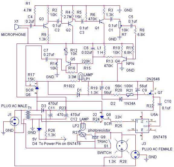
In summary, the modern whistle switch design can enhance the original concept by utilizing contemporary components such as active filters and microcontrollers, improving performance and reliability while maintaining the core functionality of the original design.The whistle switch allows you to turn on, or off, an appliance by whistling at it. I originally built the whistle switch in 1974. Do not attempt to duplicate it from the schematic below, but instead, understand the functions and duplicate these functions with more modern components. The audio amp, after the microphone, should have enough gain to produce square waves from input noise. The LC tuned circuit can be replaced by an active bandpass filter, at the frequency that you whistle the easiest.
The detector has a slow attach, fast d 🔗 External reference
Related Circuits
This circuit will light a lamp at a remote location when the doorbell switch is pressed. This circuit should only be used with the solenoid type doorbells; the electronic type that play tunes will not work here. It is...
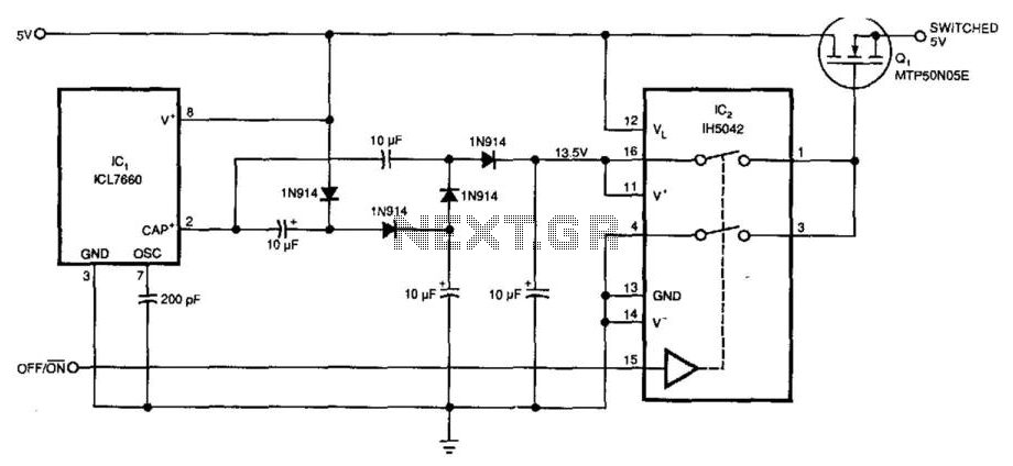
Requiring only 10 µA of quiescent current, the circuit produces an ON-resistance of only 0.1 ohm. IC1 serves as a charge pump voltage converter to generate a 5V level, allowing analog switch IC2 to provide a 10V swing to...
An ultra-sensitive gauss meter circuit schematic serves as a simple indicator with no measurement, scaling, or accuracy. It consists of a Hall effect device or integrated circuit on a board with power supply inputs, minimal signal conditioning comprising approximately...
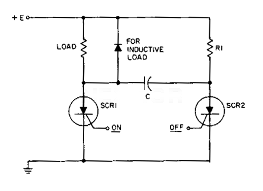
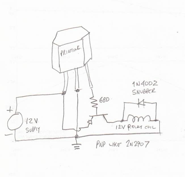
This circuit is a static SCR switch designed for use in a DC circuit. When a low-power signal is applied to the gate of SCR1, this SCR is triggered, allowing voltage to be applied to the load. The right...
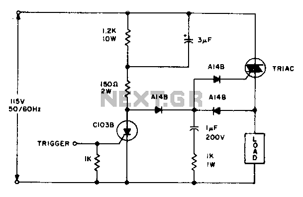
The triac will be activated at the beginning of the positive half cycle due to the current flowing through the 3 µF capacitor, provided that the C103 SCR is in the off state. The load voltage subsequently charges the...
The Elect. Sel. 8 is a simple circuit, with a choice of 8 sources of any sort, of 8 independent switches. Each switch corresponding with a relay for example the switch S1 activates the RL1 etc. The uses of...