
Latching Ac Solid-State Relay
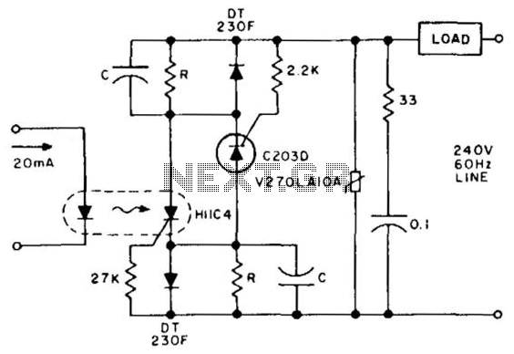
In this electronic circuit, the latching mechanism is established through the strategic use of capacitors that store energy from the gate trigger during the preceding half-cycle of the AC signal. This approach allows for the control of the power supply to a load by employing silicon-controlled rectifiers (SCRs) which require proper triggering to maintain conduction.
To effectively implement this design, the resistor (R) and capacitor (C) values must be carefully calculated to minimize energy dissipation while ensuring that the SCRs receive adequate triggering in each cycle of operation. The choice of these components directly influences the efficiency and responsiveness of the circuit.
The H11C4 optoisolator plays a crucial role in this configuration. By delivering a current pulse of over 10 ms into the infrared LED (IRED) within the optoisolator, it effectively triggers the latching relay. This relay, in turn, controls the power to the load. The timing of the current pulse is critical, as it must be sustained long enough to ensure reliable triggering of the relay while avoiding unnecessary power loss.
Overall, this circuit design emphasizes the importance of component selection and timing in achieving efficient latching control of power loads, ensuring that the system operates reliably under varying conditions. Latching is obtained by storing the gate trigger energy from the preceding half cycle in the capacitors. Powe r must be interrupted for more than one full cycle of the line to ensure turn-off. Resistor R and capacitor C are chosen to minimize dissipation, while assuring triggering of the respective SCRs for each cycle. A pulse of current, over 10 ms duration into the H11C4 IRED, ensures triggering the latching relay into conduction.
🔗 External reference
Related Circuits
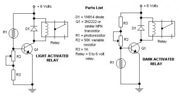
The potentiometer adjusts the trigger level. The diode in the circuit diagram is specified as 1N914, which is suitable for light-duty relays; however, since the 1N914 is a signal diode, it is not ideal for this application. A 1N4001...
The primary advantage of a solid-state relay (SSR) over a traditional electromagnetic relay (EMR) is its reduced wear and tear, which enhances its longevity. The S201S01 model from Clear-Cut serves as an exemplary representation of this technology. The following...
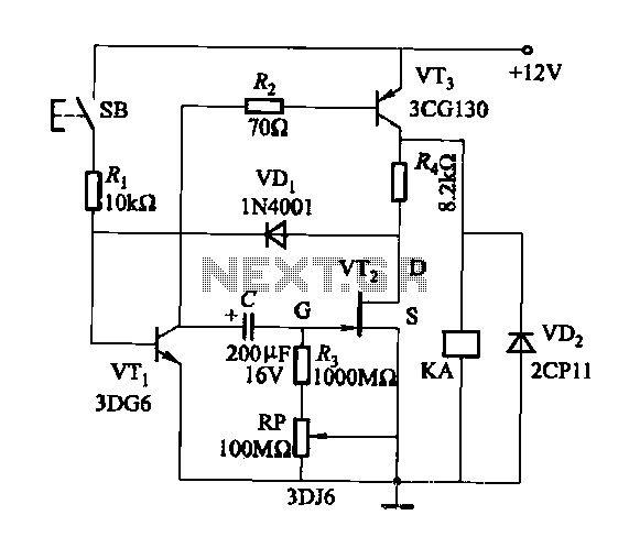
Discharge time relay circuit. The timer utilizes a field effect transistor, providing high timing accuracy and extended timing capabilities. With R3 set to 1,000,000 ohms and C at 200 microfarads, a delay time of 8 hours can be achieved....
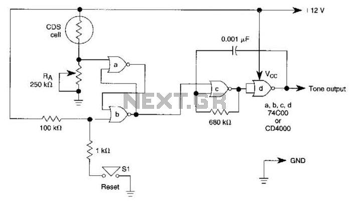
A decrease in the resistance of the CDS cell when light strikes it activates latch A and B, enabling tone oscillator C and D, which produces an output of about 1000 Hz. RA sets the trip level. SI resets...
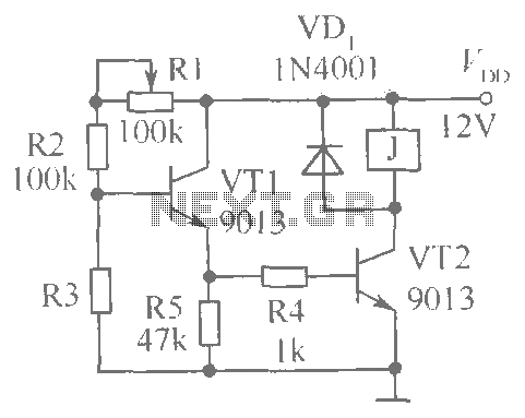
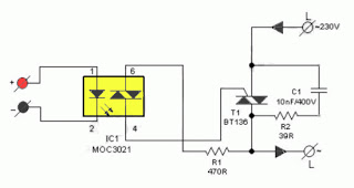
This document presents a brightness control relay circuit. Resistors R1, R2, and R3 create a voltage divider circuit with a light-sensitive resistor. When the light level drops below a specific threshold, the base voltage of VT1 increases, causing VT1...
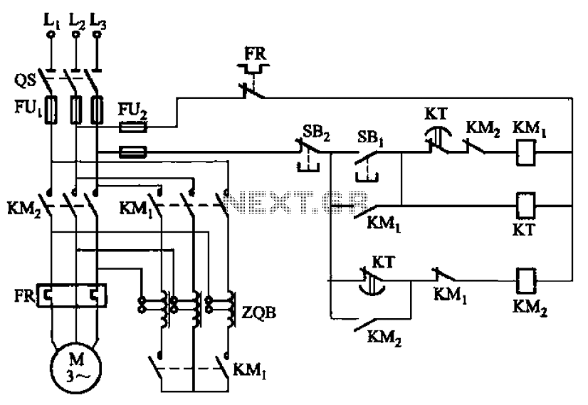
The circuit depicted in Figure 3-49 illustrates an autotransformer that is controlled by a time relay (KT). The delay time set by the KT relay corresponds to the motor's startup duration. The circuit utilizes an autotransformer, which is a type...