
latching relay circuit

The described circuit utilizes a latching relay that can be activated by logic integrated circuits (ICs) such as TTL (Transistor-Transistor Logic) or CMOS (Complementary Metal-Oxide-Semiconductor) devices. The interfacing between these logic ICs and the latching relay requires careful consideration to ensure proper operation and voltage levels.
To facilitate this interfacing, a secondary relay is employed as a trigger mechanism. This relay acts as an intermediary that converts the low-level signals from the logic ICs into a higher current signal suitable for activating the latching relay. The choice of the secondary relay should be based on its ability to handle the voltage and current levels required by the latching relay while ensuring that the control signals from the logic ICs are adequately processed.
The circuit design typically includes a flyback diode connected in parallel with the relay coil to protect the logic ICs from voltage spikes generated when the relay is de-energized. Additionally, resistors may be used to limit the current flowing into the relay coil, ensuring that the logic ICs are not overloaded.
In summary, the operation of the latching relay circuit can be effectively controlled by TTL or CMOS logic ICs through the use of a secondary relay as a trigger mechanism, providing a reliable and efficient method for interfacing between digital logic and electromechanical components.The circuit can also be triggered by logic ICs(TTL/CMOS) using proper interfacing method. I usually use another relay that serve as the trigger button when interfacing ICs to latching relay circuit. 🔗 External reference
Related Circuits
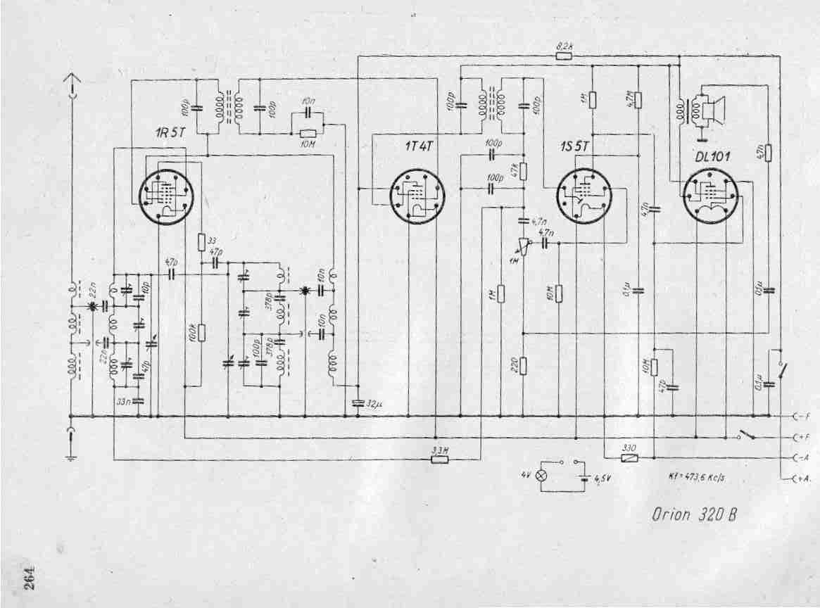
Create a repository of circuits and service data for vintage valve and transistor radios. While many resources are available online, they often come at a cost. The intention is to share circuits and manuals with others rather than profit...
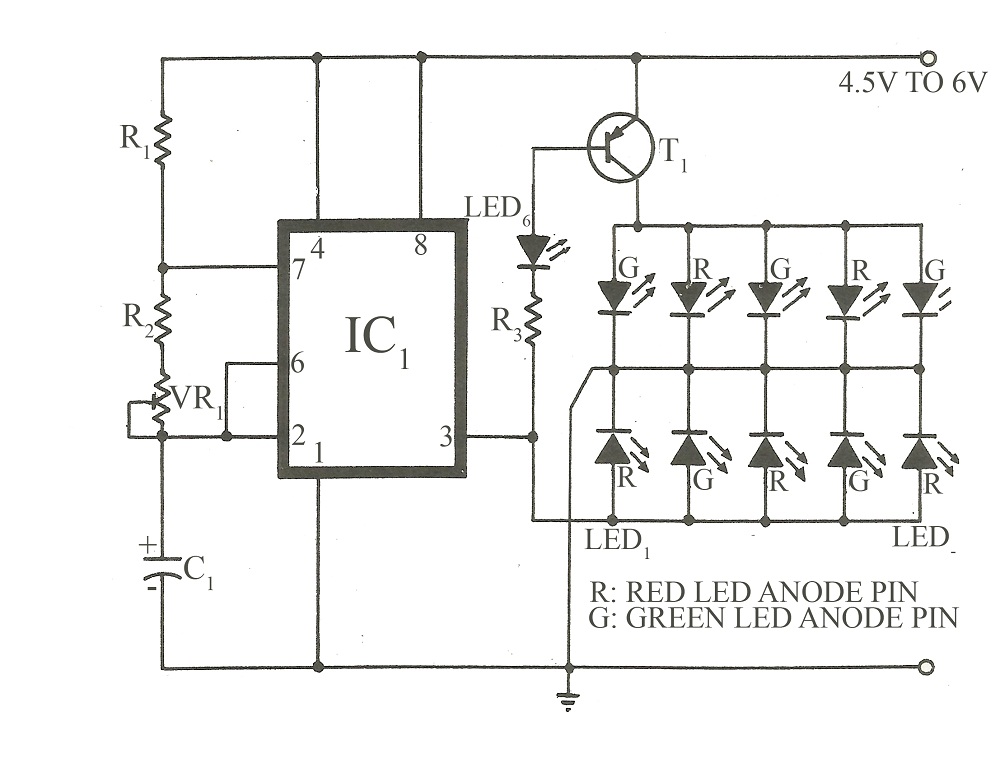
This circuit is similar to various published flasher circuits that utilize the IC 555 as a free-running multivibrator. The primary distinction is in the method of flashing bi-color LEDs. When the output at pin 3 of the IC 555...
Figure 1-89 illustrates a loudness control circuit. A potentiometer is connected to ground, with 30% of the total resistance at the tap. When the slider arm is adjusted to the tap position, a midrange attenuation of 30 dB is...
National Semiconductor (NS Company) produces audio integrated circuits (ICs) that offer wide frequency response and low noise. These circuits provide excellent performance across all NS products. The circuit illustrated in Figure 3-12 includes a preamplifier and a singing equalizer...
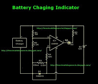
This is a battery charger indicator circuit diagram. When the battery is charging, it is indicated by an LED. This circuit can be used with a 12V battery with a charging current of less than 1A. The battery charger indicator...
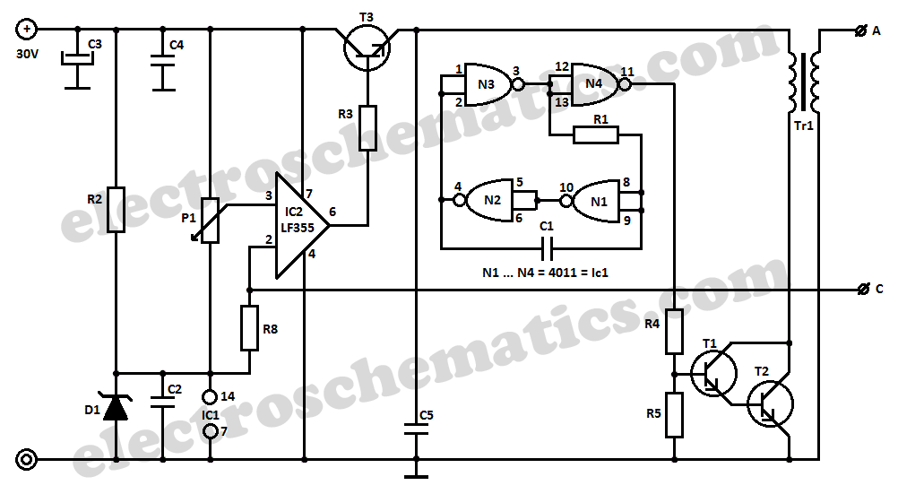
This high voltage converter circuit operates from a 30-volt power supply and can output a voltage ranging from 0 to 3 kV in version 1 or from 0 to 10 kV in version 2. The high voltage converter circuit is...