
Circuit example of the LM381

The audio circuit described integrates several key components that work together to enhance audio quality and performance. The LM381, as the central element, is designed for high fidelity and low noise operation, making it suitable for professional audio applications. The dual preamplifier configuration allows for effective isolation between channels, minimizing crosstalk and improving overall sound clarity. The incorporation of a dynamic noise reduction circuit through the LM1894 further enhances the listening experience by reducing unwanted background noise, which is particularly beneficial in environments with high ambient noise levels.
The versatility of the LM381 is evident in its ability to operate across a range of supply voltages, ensuring compatibility with various power sources while maintaining performance integrity. The significant voltage gain and output swing capabilities enable it to drive subsequent stages in audio amplification systems effectively. Additionally, the inclusion of short circuit protection and internal compensation mechanisms ensures reliability and stability during operation, safeguarding the circuit against potential damage.
In practical applications, the circuit can be configured to accommodate different audio sources, including vinyl records, CDs, and magnetic tapes, providing flexibility for users. The ability to adjust noise reduction sensitivity via a potentiometer allows for personalized tuning based on the specific audio environment, further enhancing the user experience.
Overall, this audio IC design exemplifies the integration of advanced technologies in audio processing, providing a comprehensive solution for high-quality sound reproduction in various applications. The detailed specifications and configurations outlined facilitate a deeper understanding of the circuit's capabilities and potential uses in the field of audio engineering.National Semiconductor (NS Company) production of audio ICs wide frequency response, low noise, assembled with its audio circuits, very good performance in all NS o The company integrated circuit shown in Figure 3-12. Enter Pre and sing equalizer to use LM381, dynamic noise reduction using the LM1894, LM10350 LM381 DC volume control using a wide -band, high-gain, low noise amplifier circuit, which is designed for small signal amplification design of special Dual front amplifying circuit. Its low noise, when the signal source resistance Rs = 600fl, frequency IOHz ~ lOkHz, equivalent noise input Valid values 0,5r.eVo LM381 in a variety of measuring devices, small signal amplifiers and various broadband signals source circuit is widely used o in practical applications, an external bias adjustment, enable it to achieve the best noise characteristics become broadband, high gain, low noise, high-quality amplifiers.
Shown, LM381 application circuit shown in Figure 3-14 its internal circuitry and pin arrangement shown in Figure 3-13. Internal LM381 consists of two separate pre-amplifier input, 60dB isolation between each other and with internal power source decoupling circuit and has 120dB power supply rejection very high voltage gain ( lOOdB) ratio o LM381, large output voltage swing and a large signal bandwidth (small signal bandwidth 15MH, large signal bandwidth 75kH).
9V ~ 15V it can work under a wide power supply voltage, and short circuit protection and internal compensation has finished Bodhisattva. Electrical characteristics as shown in Table 3-2. That is half of the LM381 IC2 composition phono equalizer amplifier, and the other half that is composed of IC1 line, CD player, a magnetic tape playback input amplifier, can switch SAi by selecting them individually to the input.
LM1894 dynamic noise reduction circuit, the output signal from the noise after 4,11 feet (left and right channel) o Output Select switch for selecting noise SAz whether access circuit 05 feet have connected the potentiometer for 1kfl adjust the noise reduction sensitivity O LM1035 dual-channel DC volume control potentiometer, at its output end that loudness volume control potentiometer and switch J.
Related Circuits
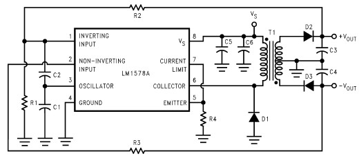
This RS232 power supply circuit diagram is a simple RS-232 line driver power supply that operates from an input voltage as low as 4.2V and delivers an output of ±12V at ±40 mA with an efficiency of better than...
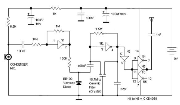
Logic Gates FM Transmitter Circuit Electronic Circuit Schematic Wiring Diagram. The FM transmitter circuit utilizing logic gates is a fundamental electronic design that operates by modulating a carrier frequency with an audio signal. This circuit typically consists of various logic...
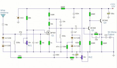
This is a booster antenna circuit designed for frequencies ranging from 550 kHz to 1650 kHz, aimed at amplifying signals received from a telescopic antenna. It covers the medium waveband within this frequency range. To drive low impedance (50...
This circuit gives a low-level output when sufficient lighting is present, functioning as a light detector. It can issue a command to turn on lights when darkness falls. Its output is compatible with TTL levels, providing a low logic...
The total gain of the car antenna amplifier is approximately 30 dB, with an input impedance of around 10 kΩ at 30 MHz. The amplifier should be mounted directly at the base of the antenna to prevent signal losses...
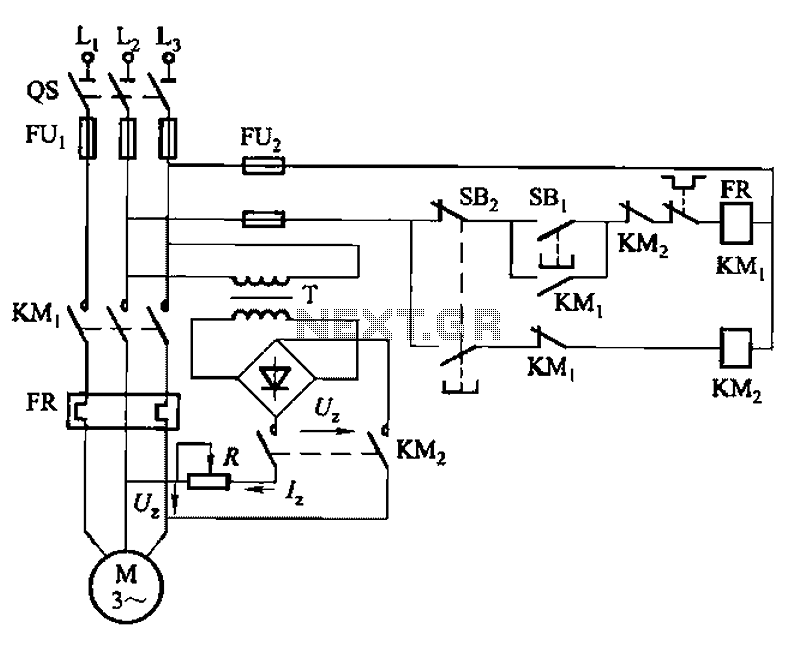
The 3133 circuit is illustrated in Figure 3-133. It features dynamic braking controlled manually via buttons in three separate lines. In part (a) of the figure, the dynamic braking DC power supply is depicted with a step-down transformer and...