
latest touch alarm system circuit
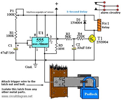
The circuit described utilizes a 555 timer integrated circuit configured in monostable mode to create a touch-sensitive relay activation system. The 555 timer is powered by a 12V DC power adapter, ensuring that the voltage levels are compatible with standard electronic components. The choice of a relay is flexible, allowing for various types to be used based on the specific requirements of the application, such as current rating and switching capacity.
Capacitors C1 and C2 are critical for stabilizing the voltage and ensuring reliable operation. Their voltage ratings must be appropriately selected to handle the maximum expected voltage, which, in this case, is at least 25V to accommodate the 12V power supply. The selection of a transistor for T1 can be made from a range of NPN or PNP transistors that can handle the relay's coil current.
The RESET switch, typically a normally closed type, provides a manual method to reset the system, ensuring that the relay can be deactivated when needed. The touch-sensitive trigger wire connected to pin 2 of the 555 timer is designed to detect changes in resistance when a user touches it, thus triggering the relay. The design emphasizes the importance of maintaining a clean contact surface for reliable operation.
In terms of layout, the circuit should be arranged to minimize noise interference, particularly in environments where electrical noise may be present. The optional capacitor between pin 5 and ground can help filter out any high-frequency noise that could affect the stability of the timer. The built-in delay mechanism is an important feature that prevents unintentional activation of the relay, providing a buffer period that can differentiate between accidental touches and intentional activation.
Overall, this circuit serves a practical purpose in security applications, particularly in educational environments, by providing a deterrent against tampering with sensitive equipment.C1/C2 operating voltage should be elevated to 25V if you decide to go with a 12V energy source. Rule of thumb: the operating voltage of capacitors are at least double the supplied voltage, in other words, if the powersource is 9Volt, your capacitor(s) is a minimum of 18V. Transistor T1 could be any approximate substitute. * Use any suitable r elay for the project and if you are not tight on area, use any size. I`ve develop this specific circuit to prevent students from fiddling using the security cameras in pc labs in the University I`m employed. I made certain the metal casing was not grounded. But as the schematic shows you can essentially hook it as much as any type of metal surface. I utilized a 12-vdc power adapter. Use any appropriate relay to handle your requirements. A RESET` switch (Usually Closed) can be added between the constructive and the arrow-with-the-+`. The trigger (touch) wire is connected to pin 2 of the 555 and will trigger the relay, utilizing the body resistance, when touched.
It is apparent that the touching` component has to be clean and can make good get in touch with with the trigger wire. This particular circuit may not be suitable for all applications. Just in case you wonder why pin 5 isn`t listed within the schematic diagram; it isn`t truly required.
In certain noisy conditions a little ceramic capacitor is placed in between pin 5 and ground. It does no harm to add one or leave it out. Extra note: For all those of you who didn`t discover, there is an approximate 5-second delay build-in prior to activation of the relay to avoid false triggering, or a would-be` thief, etc. 🔗 External reference
Related Circuits
This small transmitter can reach distances of more than 1 km under favorable transmission conditions. Modulation can be achieved using a microphone, such as an electret microphone, or another audio source. The transmitter includes a coil made of 5...

This circuit is the simplest inductive balancing metal detector (IB, Induction Balance) that can be constructed. The LB metal detection method offers satisfactory depth of penetration and effectively distinguishes between iron-based and noble metallic objects. While several metal detectors...
This circuit features an adjustable output timer capable of re-triggering at specified intervals. The output duration can range from a fraction of a second to over half an hour, with the ability to recur at regular intervals spanning from...

A high-power and efficient 100W power amplifier electronic project can be designed using the STK404 audio power amplifier hybrid ICs. These ICs consist of optimally designed discrete component power amplifier circuits that have been miniaturized using SANYO's unique insulated...
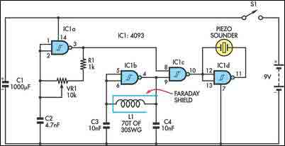
The circuit incorporates two oscillators, both operating at about 40kHz. The first, IC1a, is a standard CMOS oscillator with its frequency adjustable via VR1. The frequency of the second, IC1b, is highly dependent on the inductance of coil L1,...

This is a single-zone alarm system featuring independently adjustable Exit, Entry, and Siren Cut-Off timers. It is compatible with standard normally-closed input devices such as magnetic-reed contacts, foil tape, and passive infrared sensors (PIRs). A mains power supply can...