
Repeating Interval Timer circuit
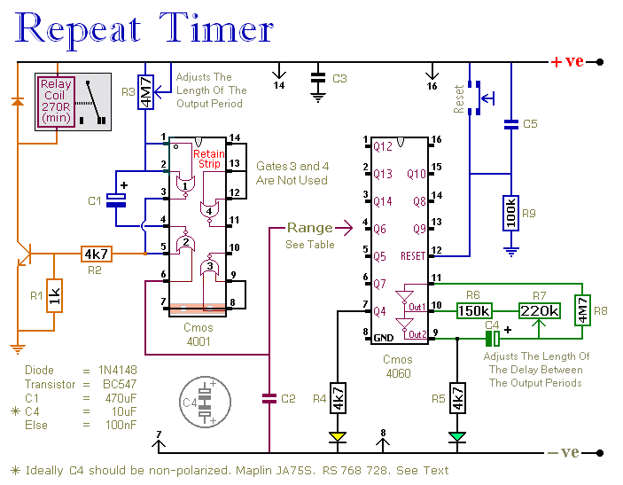
The adjustable output timer circuit utilizes a combination of resistors, capacitors, and a timer IC, such as the NE555 or similar, to achieve its functionality. The core of the circuit is the timer IC configured in astable or monostable mode, depending on the desired operation. In astable mode, the circuit continuously oscillates between high and low output states, while in monostable mode, it generates a single pulse when triggered.
To adjust the timing intervals, variable resistors (potentiometers) and capacitors are employed. The time period for the output signal can be calculated using the formula T = 1.1 * R * C for monostable mode, where T is the time period, R is the resistance in ohms, and C is the capacitance in farads. By selecting appropriate values for R and C, the output period can be finely tuned to meet specific requirements.
The circuit may also include additional components such as diodes for protection, transistors for amplifying the output signal, and relays for switching larger loads. The design should ensure that all components are rated appropriately for the voltage and current levels expected in the application.
For applications requiring longer timing intervals, it is possible to cascade multiple timer circuits or use a microcontroller to achieve greater flexibility and precision in timing. The microcontroller can provide programmable timing intervals and can be interfaced with various sensors or control systems for advanced applications.
Overall, this adjustable output timer circuit is versatile and can be adapted for numerous applications, including automated lighting systems, irrigation timers, and industrial control systems, where precise timing and re-triggering capabilities are essential.This circuit has an adjustable output timer that will re-trigger at regular intervals. The output period can be anything from a fraction of a second to half-an-hour or more - and it can be made to recur at regular intervals of anything from seconds to days and beyond.. 🔗 External reference
Related Circuits
The circuit consists of a 555 timer IC configured as a multivibrator, which operates with two probes to measure the water level. When the capacitance between the probes indicates a high water level, the output from the 555 timer...
The IRF9540N Gate Charge Test Circuit is illustrated in the diagram below. The IRF9540N is recognized as a rectifier device that employs advanced processing techniques to attain an exceptionally low on-resistance per unit area, as stated in the datasheet....
The built-in temperature sensor is utilized to control the triac TC620 for temperature regulation. The adjustment circuit, consisting of resistors Rp1 and Rn, allows for modifications to the lower temperature limit. When the ambient temperature exceeds this lower limit,...
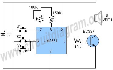
The circuit under discussion is a four-siren sound generator utilizing the UM3561 integrated circuit (IC), which is a low-power CMOS device. Four distinct sounds can be generated by activating switches S1, S2, and S3. This circuit is versatile and...
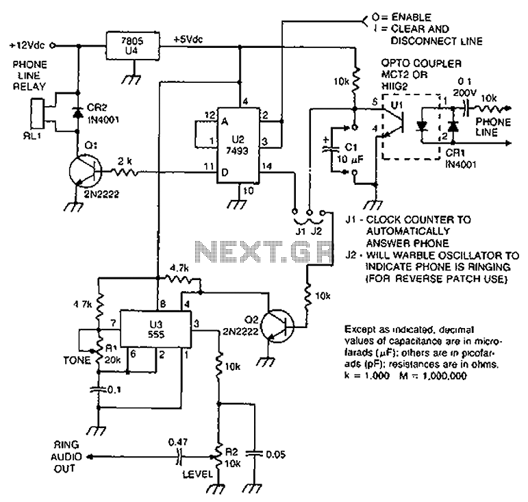
Check the loop circuit for an automatic telephone answering system or a tone generator for use in reverse automatic repair. The loop circuit in an automatic telephone answering system is designed to detect incoming calls and activate the answering mechanism....
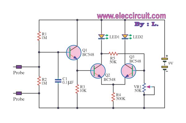
This is a false capture circuit or lie detector circuit. The basic principle is based on the resistance of human skin. While dry skin has a resistance of about 1 Megaohm. The lie detector circuit utilizes the principle of galvanic...
Warning: include(partials/cookie-banner.php): Failed to open stream: Permission denied in /var/www/html/nextgr/view-circuit.php on line 713
Warning: include(): Failed opening 'partials/cookie-banner.php' for inclusion (include_path='.:/usr/share/php') in /var/www/html/nextgr/view-circuit.php on line 713