
Circuit of power fm transmitter transistor 2n2218 audio wireless 1KM
The described transmitter circuit operates on the principle of amplitude modulation (AM) or frequency modulation (FM), depending on the configuration of the audio input. The use of an electret microphone allows for effective audio signal capture, which is then modulated onto a carrier frequency. The 22 AWG enameled wire coil, consisting of five turns, serves as the inductor for the oscillator circuit, which is crucial for generating the RF signal. The diameter of the coil is specified to ensure optimal inductance and resonance at the desired frequency.
Ceramic capacitors are employed in the circuit due to their stability and reliability in high-frequency applications. The choice of antenna length is critical, as it influences the range and efficiency of the transmission. The recommended length of 15 to 40 cm is based on the operating frequency and the physical characteristics of the antenna, which should be matched to the transmitter's output for maximum performance.
The FM receiver must be tuned to a frequency that is not occupied by other radio signals to minimize interference. The adjustment of the CV screw allows for fine-tuning of the transmitter's output frequency, ensuring that the signal can be optimally received. The use of a wooden or plastic tool for this adjustment helps avoid any additional capacitance that could affect tuning.
The transistor 2N2218 is a critical component in the circuit, functioning as the amplifier for the modulated signal. Proper attention to the pinout configuration is necessary to ensure correct operation. The resistor R1 is integral to the microphone's operation, providing the necessary biasing. The ability to adjust R1 allows for compatibility with different microphone models, ensuring that the audio signal is appropriately amplified before modulation.
Utilizing a fiberglass board for mounting the components enhances the circuit's performance at high frequencies, reducing potential losses and maintaining signal integrity. The suggestion to connect the antenna to the second turn of the coil can further stabilize the frequency output, ensuring consistent transmission quality. This detailed understanding of the circuit components and their interactions is essential for successful transmitter design and implementation.This small transmitter can arrive the more than 1 km in favorable conditions of emission. The modulation can be made so much with a microphone, for an electrets microphone, or other audio source. The 5 turns of enameled thread 22 AWG, with diameter of 1 cm without nucleus. Look at the capacitors that it should be ceramic. The antenna should posses s from 15 to 40 cm. Para the transmission it ties a receiver of FM (radio) in the proximities to half volume in a free frequency (that there is not any radio operating), with a wood or plastic key, rotate the screw of CV to capture the sign more fort of the transmitter, because a spurious sign can be captured. If it has difficulties of fittings, remove the coil and wind her again with more or less it turns. Look at pinage of the transistor 2n2218. Mic1 is a microphone of electrets of two terminals, THE resistor R1 makes the polarization of the microphone, perhaps it is necessary to alter the value of R1 to adapt to your microphone, values of 1k up to 10k can be tested.
Preferably use plate of glass fiber, that is the appropriate for high frequency. Perhaps for better frequency stability to be necessary to place the antenna on second turn of the coil, weld the thread piece used as antenna second it turn of the coil L1. 🔗 External reference
Related Circuits
This transmitter originated as a conventional shunt-fed Hartley oscillator for 80 meters, utilizing a pair of 27 triodes connected in parallel. With 300 VDC applied to the plates of the 27s, it produced approximately 4 watts of output with...
The two circuits below illustrate the application of the 555 timer to activate a relay for a specified duration by pressing a momentary normally open (N/O) push button. The circuit on the left can be used for longer time...
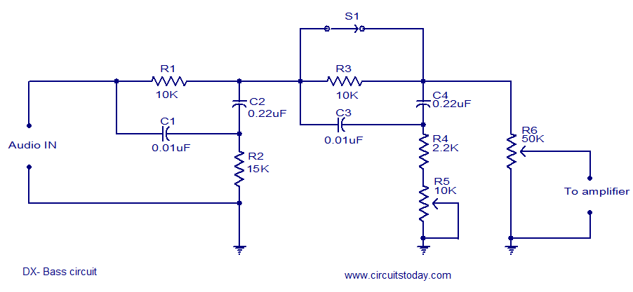
The circuit diagram of a passive DX bass circuit is presented, which is compatible with nearly all audio amplifiers. This design was created by Mr. Emmanuel Chipula from Malawi and submitted for publication. Laboratory tests confirmed satisfactory performance. Credit...
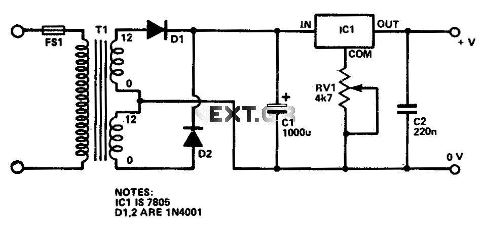
This circuit provides a regulated output voltage ranging from 5 V to 15 V DC, which can be adjusted using a preset resistor. The current output can reach up to approximately 350 mA. An integrated circuit is utilized to...
A potentiometer regulates the firing point of the triac. Capacitor C4 is charged through resistors R3, R4, P1, and R5. After a specific duration, determined by the potentiometer setting, the charge in C4 becomes sufficient for the diac D...
An astable multivibrator, also known as an oscillator circuit, operates on the principle of positive feedback. This type of circuit can be constructed using operational amplifiers, logic gates, or transistors. An astable multivibrator is a fundamental electronic circuit that generates...