
LCD Car Accelerometer
Before measurements commence, an initialization process is performed, which involves taking 16 measurements and calculating their mean. During this short interval, it is assumed that acceleration remains unchanged, providing a reference point for null acceleration. In essence, the duty cycle corresponding to null acceleration is established and subsequently subtracted from each measurement. Upon activating the starter switch, the circuit powers on. Initially, while the LED is off, the meter undergoes initialization. The accelerometer must be oriented to measure acceleration in the direction of the vehicle's movement. Regardless of the orientation, a vertical component due to gravity will always be present and must be accounted for in measurements. Once the LED illuminates (after a minimal time), initialization is complete, and the meter begins measuring acceleration, displaying the results on the screen. A negative sign indicates deceleration.
Additionally, the upper section of the screen displays the total time interval that the vehicle has been in operation. This clock operates based on vibrations detected at the External Interrupt 0 pin from an external circuit utilizing the LM555 timer.
Future iterations of this circuit may include a second output from the accelerometer to measure centripetal acceleration during vehicle movement. When positioning the device, the ADXL202 should be aligned parallel to the ground, with pins 1 and 14 facing the front of the vehicle. The LCD is connected to the K2 connector, while the ADXL202 connects to the K1 connector (K3 is also connected to K1).The circuit is drawn for measurement of acceleration from 1000 mg until + 1000 mg. It can be placed in kantra'n the car and be supplied from the sheath of electric lighter. The circuit includes one indicative LED and a screen LCD. The measurement of acceleration becomes with the use of IC from Analog Devices, the ADXL202. The particular element contains 2 autonomous vertical between them sensors, for the measurement in two axes. For the particular application becomes use of only it's one. Acceleration meter measures dynamic or static acceleration from 2g until 2g (where g is the acceleration of gravity) and when this is equal to zero, exit is a signal PWM, with Duty Cycle 50%.
As long as the acceleration increases, increases also the Duty Cycle, with biggest response the 75% (in the 2g), while for acceleration 2g, the Duty Cycle is 25%. As conclusion from more, has that for change 1g, is altered also the Duty Cycle of exit at 12,5%. The measurement of Duty Cycle of response of acceleration meter becomes with the help of Timer1 (16 bit).
The period of signal of expense, has been fixed in the 1,12 msec. The frequency of oscillation of microcontroller is in the 3,6864 MHz and this means that it's each circle of access lasts 0,27 * 10 -6 sec. Using timer1, in frequency of measurement ck/1, the biggest feasible counted time is the 65536 * 0.27 * 10 -3 msec = 17.778 msec, which is bigger than period (1,12 msec).
So, any price Duty Cycle it is possible to be measured. Before the beginning of measurements, it precedes a process of accelerator?s initializing. At this process it is doing 16 measurements, and then is found their mean. In short time interval, it is considered that the acceleration was not altered also thus the result, us gives the point of null acceleration. In other words at this process becomes approach of value Duty Cycle, that corresponds in null acceleration.
From now on, after each measurement, it will be removed from Duty Cycle, the null acceleration. With the shooting of switch of starter, the circuit is supplied. In the beginning, and as long as LED is power-off, becomes initializing of meter. Acceleration meter is will be always placed so as to it measures the acceleration at the address of movement of vehicle. As long as however well and it is placed this, will always exist a component vertical in the movement and with time to the centre of ground.
This component is the acceleration of gravity and which is always removed from each measurement. As soon as the LED turns on (in minimal time), then the initializing it has become. From now on the meter measures the acceleration and him presents in the screen. When is presented the symbol "-", it means that it is deceleration. In the above department of screen is presented the clue of total time interval, that your car is in operation. The operation of this clock is based on vibrations that come in the pin External Interrupt 0, from exterior circuit based in the timer LM555.
In the future it is is published new circuit, with the himself characteristically, that will use the second exit acceleration meter, for the measurement of centripetal acceleration, at the movement of car. At the placement of appliance, the completed ADXL202 should be always parallel with the surface of ground and the pins 1 and 14 they see front part of car.
The LCD is connected at the K2 connector and the ADXL202 is connected at the K1 connector (K3 is connected with K1). 🔗 External reference
Related Circuits
The 567 IC tone decoder/detector can be utilized to construct a remote control or intercom system. This circuit is capable of controlling a relay or transmitting an audio signal. The 567 IC is a versatile component often employed in tone...
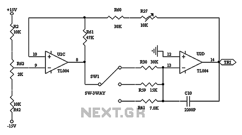
The triangular wave circuit consists of two operational amplifiers (OPs). R62 serves as the offset adjustment, while R27 is utilized for peak adjustment. A switch is included to select different resistances, allowing for the generation of triangular waves at...
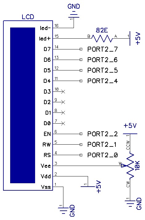
The circuit utilizes a total of seven pins from the microcontroller's GPIO. Consequently, the LCD module requires only one port out of four available. The EN line, known as "Enable," is a control line that indicates to the LCD...
The circuit schematic is straightforward. Information regarding the assembly and testing of circuits is not provided, as there are many instructional resources available. The circuit schematic in question is designed to be simple and user-friendly, allowing for ease of understanding...
This document provides an example of how to interface with the standard Hitachi HD44780 LCD using an 8051 microcontroller and the SDCC C compiler. A standard 16-character by 2-line LCD module is utilized, as illustrated in the schematic below....
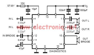
In practical applications, a series resistance must always be included. This component serves the dual purpose of limiting the current at pin 7 and smoothing the ON/OFF transitions during standby. In electronic circuits, particularly those involving integrated circuits (ICs) or...