
LCD Display with Microcontroller
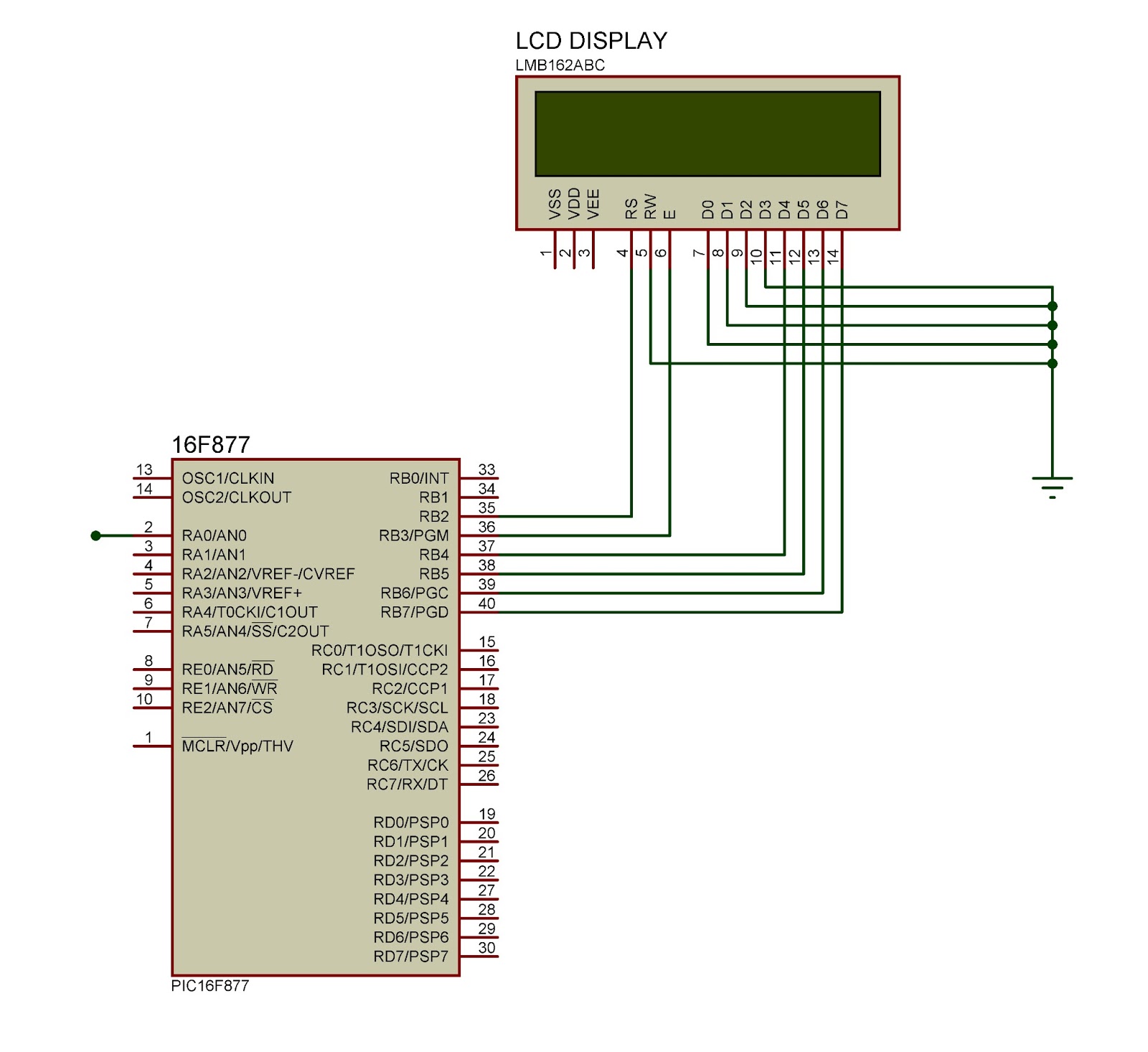
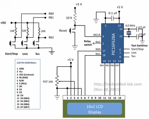
The power supply for the LCD display consists of two 5V DC sources. The primary power supply connects to the VSS and VDD pins. The second power supply is for the backlight, which connects to pins 15 and 16; this backlight power supply is optional if the application does not require operation in low-light conditions.
The VEE pin requires a 5V supply through a variable resistor (preset). Adjusting this preset allows for control over the brightness of the displayed text. If this supply is not connected, the text on the LCD may not be visible.
Data pins D4 to D7 are utilized, although only four pins (D0 to D3) are necessary at this stage. The RS, E, and D0 to D3 pins should be grounded. Any port from the microcontroller (e.g., PORTB, PORTC) can be selected for the connection, allowing flexibility in pin assignment. The connections do not need to match the diagram precisely, and any configuration can be used. The initialization of the microcontroller pins for the LCD can be accomplished using microC Pro code.
The 16x2 LCD display is an essential component for visual output in many embedded systems. Its ability to present alphanumeric characters makes it suitable for various applications, from simple status displays to more complex user interfaces.
The primary connections include the VSS pin to ground and the VDD pin to a 5V power supply, ensuring the basic operation of the LCD. The optional backlight can enhance visibility in dim environments, connecting to the appropriate pins as needed.
The VEE pin's brightness control is critical for optimizing readability; without this connection, the display may be too dim or entirely blank. The use of a variable resistor allows for fine-tuning based on the ambient lighting conditions.
The data pins (D0 to D3) facilitate communication between the LCD and the microcontroller. The RS (Register Select) pin determines whether the operation is a command or data transfer, while the E (Enable) pin is crucial for executing the commands sent to the LCD.
Flexibility in the microcontroller's port selection allows for adaptability in circuit design, accommodating various configurations based on the project's requirements. The initialization code provided by microC Pro simplifies the setup process, ensuring that the microcontroller can effectively communicate with the LCD display.
Overall, this configuration provides a robust foundation for integrating a 16x2 LCD display into microcontroller-based projects, enabling effective user interaction and data presentation.Here I have described how to connect a 16 by 2 LCD display to a microcontroller. Here I have demostrated it with very common pic 16F877A. This is the circuit diagram. Here I haven`t showed the power supply and oscillator connection for pic and LCD. LCD normally have 16 pins. If you carefully observed you can see number 1 or 16 have printed near th e related pin. First let`s start with power. LCD display mainly two 5V DC power supplies. Main power supply should connect to VSS and VDD pins. Other power supply is for turn on backlight. Those pins are pin 15 and 16. They haven`t been shown in the figure. Backlight power supply is not necessary if we are not going to work in a dark environment. Ok now power supply is done. VEE pin should supply 5Vs through a preset(Variable resistor). By adjusting preset we can change the supply power to the VEE pin. It controls the brightness of the displayed text. If you are not connected this supply some times you may not see text on LCD. D4 to D7 are data pins. We only need 4 pins from them at this stage(D0 to D3). RS, E and D0 to D3 pins should be connected to the earth. Select any port(Eg. PORTB, PORTC whatever) from microcontroller. Connect pins shown in the figure to any pin as you want on that port. Connection dont`t want to be same as the figure. You can use any configuration. We can use microC pro code to initialize microcontroller pins for LCD pins. 🔗 External reference
Related Circuits
The advanced credit card, referred to as the "microcontroller super card," incorporates numerous innovative enhancements. The initial step involved verifying the code and subsequently uploading it to the Arduino board. The developed code enabled a counter to increment from...
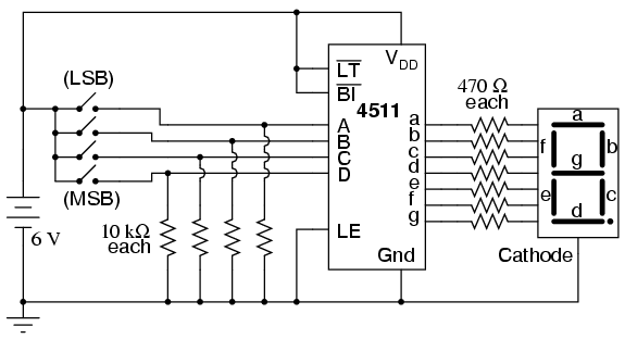
This experiment serves as an introduction to the 4511 decoder/display driver IC rather than a lesson on constructing a digital function from lower-level components. Given the prevalence of 7-segment displays in digital devices, it is beneficial to understand the...
This is an easy-to-build yet highly accurate digital voltmeter designed as a panel meter for use in DC power supplies or any application requiring precise voltage indication. The circuit utilizes the CL7107 ADC (Analog to Digital Converter) IC manufactured...
A source code for a simple PIC-based digital timer is provided. The hardware for the project is not available; however, it will be demonstrated using a DIY PIC16F628A breadboard module and I/O board. The complete circuit diagram and firmware...
This circuit demonstrates a dynamic AC signal level display drive, which can be utilized for audio level display purposes. The AC signal detection and drive control are achieved using the BA6124 integrated circuit, along with five external colored light-emitting...
A wide range frequency meter is a useful tool for an electronics lab. This project describes a frequency meter based on the AT90S231 microcontroller that can measure input frequencies up to 50 MHz. The measured frequency is displayed on...
Warning: include(partials/cookie-banner.php): Failed to open stream: Permission denied in /var/www/html/nextgr/view-circuit.php on line 713
Warning: include(): Failed opening 'partials/cookie-banner.php' for inclusion (include_path='.:/usr/share/php') in /var/www/html/nextgr/view-circuit.php on line 713