
LCD projector multi-function controller circuit diagram

The LCD projector multi-function controller circuit is engineered to monitor and regulate the temperature of the halogen lamp, thereby enhancing the longevity and performance of the LCD screen. The core components of the circuit include diodes (VD1 to VD4) that serve as protection elements to prevent reverse polarity and voltage spikes, ensuring the integrity of the circuit.
The integrated circuit (IC1) acts as the central processing unit, managing the inputs from temperature sensors and controlling the output signals to the other components in the circuit. Capacitor C1 is used for filtering and stabilizing the voltage supply, contributing to the overall reliability of the circuit operation.
Transistor VT1 functions as a switch that regulates the power supply to the halogen lamp based on the temperature readings from the sensors. When the temperature exceeds a predetermined threshold, the controller reduces the power to the lamp, thereby lowering its temperature and preventing damage to the LCD screen.
This multi-function controller circuit is crucial for maintaining optimal operating conditions within the projector, ensuring that the LCD screen remains protected from excessive heat. Proper implementation of this circuit can significantly extend the operational life of LCD projectors, making it an essential component in their design and production.In the production of LCD projector, the main factors of the threatening life of LCD screen is the temperature of halogen. The multi-function controller made by this circuit is very effective for the protection of liquid crystal projector.
The LCD projector multi-function controller circuit is shown as below. The circuit composed of VD1 ~ VD4, ICl, C1, VTl.. 🔗 External reference
Related Circuits
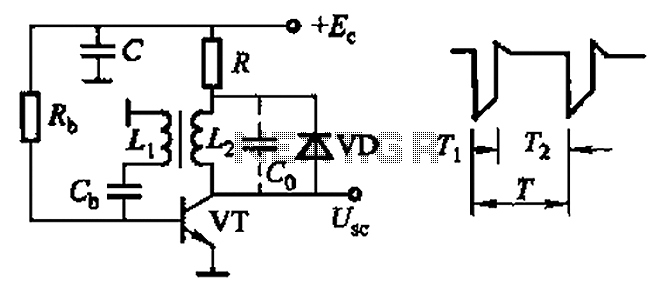
Common non-sinusoidal oscillator circuit, waveform and frequency formula - sawtooth oscillator - use blocking oscillator The sawtooth oscillator is a type of non-sinusoidal oscillator that generates a waveform characterized by a linear rise in voltage followed by a rapid drop....

The multi-purpose signal generator circuit consists of integrated circuit oscillators and frequency dividers. It generates square waves ranging from high frequencies to sub-audio frequencies and also produces a frequency standard in the VHF range. The alternative oscillator section feeds...
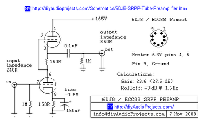
This is one of many available variations for a Symmetrical SRPP Preamplifier based on the 6DJ8 / ECC88 family of tubes. The SRPP circuit has also been referred to as a SEPP, Totem Pole, Mu Follower, Mu amplifier, and...
Incremental rotation or linear encoders are widely used, but they typically do not provide a direction signal. This design presents a straightforward method to detect forward or reverse direction. Incremental encoders usually generate two output signals, referred to as...
It's a very simple circuit, for the follow-up of baby. It can however be also used for other use, as intercom etc. In the place of M1 we can we use a simple electret mic capsule. The regulation of...
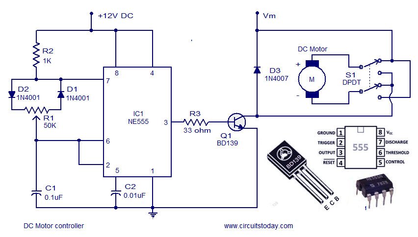
A DC motor controller based on an NE555 timer is presented here. The direction of rotation of the DC motor can also be changed using this DC motor speed control circuit. The described circuit utilizes the NE555 timer IC in...