
LCD power supply circuit
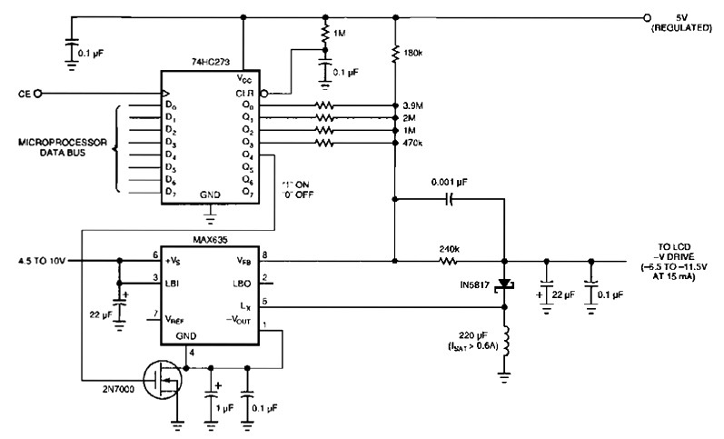
The switching regulator circuit described is designed to provide a negative voltage output from a positive voltage source, specifically utilizing the notebook battery supply. The core component of the circuit is the 4-bit digital-to-analog converter (DAC), which is capable of generating a range of output voltages by varying the resistance in the circuit. The 74HC273 DAC is interfaced with the microprocessor data bus, allowing for digital control of the output voltage, which can be adjusted in 16 discrete levels between 6.5 V and 11.5 V.
The implementation of the DAC is facilitated by a rail-to-rail output CMOS gate from the 74HC series, which ensures that the output voltage can swing close to both supply rails, maximizing the range of output voltages available for the LCD power supply. The use of a resistor divider network, including a 240-kΩ resistor, plays a crucial role in setting the output voltage by providing a reference voltage from the 5 V supply regulated by the MAX635.
This circuit is particularly beneficial for driving large-screen LCDs, which require a negative supply voltage to enhance contrast and display quality. The adjustable negative voltage output is essential for applications where varying display conditions are present, ensuring optimal performance under different lighting and usage scenarios.
The switching regulator operates with a 9 V input from a battery and delivers a stable 5 V output with an efficiency rating of approximately 80%. The efficiency is further improved in the described circuit, achieving around 85% under typical operating conditions. The key to the regulator's operation lies in the switching element, a MOSFET (BUZ71A), which is controlled by a 45 kHz signal generated by the MAX541 switching regulator IC. This high-frequency operation allows for effective energy transfer and regulation, minimizing losses that would occur in linear regulators.
The circuit's design reflects modern trends in electronics, where compact and efficient power supplies are paramount. The integration of switch-mode power supply technology enables the creation of smaller, lighter, and more efficient power solutions for portable devices like laptops, making them more versatile and user-friendly.The following figure`s switching regulator generates a negative voltage by the notebook battery supply. The microprocessor data bus drives a 4-bit DAC( 74HC273 ), which in turn can vary the regulator output between 6.
5 to 11. 5 V. This arrangement enables a staircase of 16 possible voltages between these limits. The LCD power supply circuit impleme nts the DAC by using the rail-to-rail output-drive capability of a 74 HC-series CMOS gate. A resistor divider network made by the 240-kO resistor, connected to the V filter capacitor as well as the resistors, is referenced to the 5 V supply control (the MAX635 regulator). The schematic diagram come from circuit: Simple LCD Power Supply power supply. Go to that page to read the explanation about above power supply related circuit diagram. Laptop display commonly apply large screen Lcds, which generally will need a adjustable and a negative supply to ensure highest possible contrast.
This circuit works with the system`s positive notebook battery supply and generates a digitally adjustable negative voltage to. This simple switching regulator circuit have 5 V output, the input provide by a 9 V battery. It having 80% efficiency and 50mA output capability. How simple switching Regulator works: While Q1 is actually on, its collector voltage increases, delivering current.
This DC to DC Converter use Max 541 from Maxim, IC1 is a switching regulator that generates a 45-kHz signal that drives the gate of MOSFET Q1 BUZ71A from Motorolla. The source of this power supply comes from a 12V car battery voltage. This DC to DC converter have an. Switch Mode Power Supplies (SMPS) is now widely used in modern electronic equipment due to its compact design and high efficiency of about 80% or more.
The switch-mode regulator circuit presented here has an efficiency of around 85%. The circuit. Laptops today are the what is called notebook computers, which now is becoming popular. Laptops can be brought into the bag making it suitable for business trips. And even as the "home entertainment center" laptop is more convenient, because it. We aim to transmit more information by carrying articles. Please send us an E-mail to wanghuali@hqew. net within 15 days if we are involved in the problems of article content, copyright or other problems. We will delete it soon. 🔗 External reference
Related Circuits
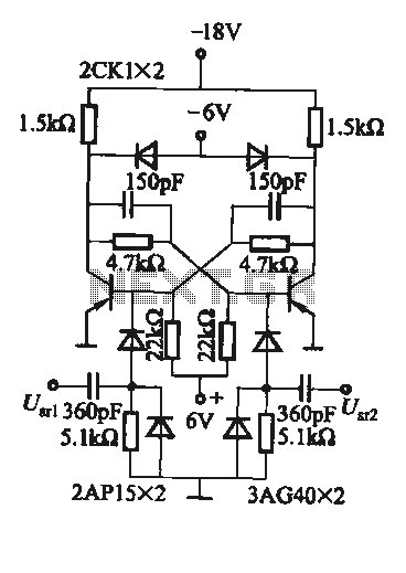
A flip-flop circuit with a memory function for pulse signals. It features two stable states: one where transistor VTi is off and VTZ is conducting, and another where VTi is conducting and VT2 is off. An external signal is...
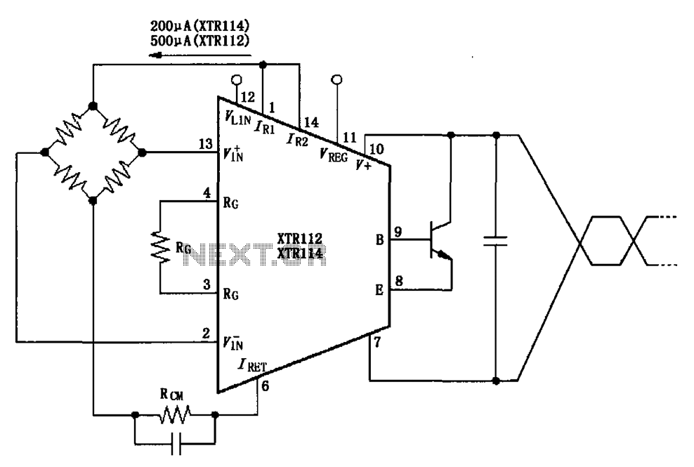
The two current sources within the chip (1 foot and 14 feet out) provide excitation. The output of each current source is 0.2 mA (XTR114) or 0.5 A (XTR112). The common mode input voltage is adjustable, ranging from 1.25...
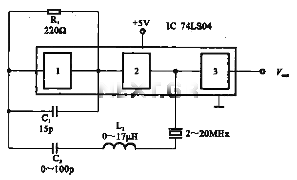
The circuit includes several gates arranged as a crystal oscillator circuit. Figure (A) illustrates a crystal oscillator circuit operating at 1 MHz, while Figure (B) depicts a 20 MHz crystal oscillator circuit. Figure (C) represents a variable crystal oscillator...
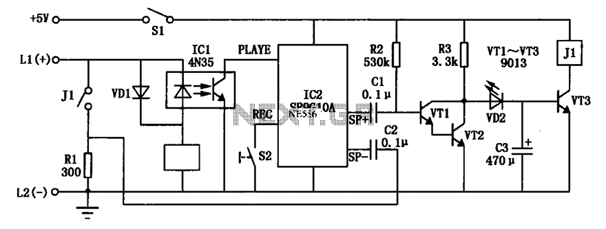
An automatic telephone responder circuit is illustrated. It incorporates a 10-second voice recording circuit (SR9G10A) activated by the power switch (S2). The circuit utilizes an electret microphone (IC2) for sound input. To initiate the response, the user must press...
Some simple 555 and flip-flop circuits are being developed to add electronic lighting effects to modernize games. Various circuits are being collected for different game aspects, such as idle states, flipper shots, flower openings, winning shots, etc. A collection...
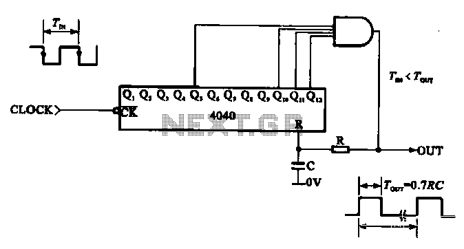
This document illustrates the application of a CMOS integrated circuit (IC) count divider, specifically the TC4040, which functions as a 12- or 14-bit counter. The circuit can be configured to achieve various frequency division ratios, such as a 1:3600...