
LDO Regulator -
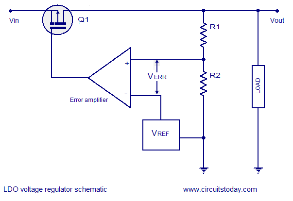
LDO (Low Dropout) regulators are essential components in power management systems, allowing for the regulation of output voltage with minimal input-output voltage differential. They are characterized by their ability to maintain a steady output voltage despite variations in input voltage and load conditions. The LM2941 is a popular LDO regulator that offers adjustable output voltages ranging from 5V to 20V and can deliver a maximum output current of 1A.
In a typical application, the LM2941 can be configured using a few external resistors to set the desired output voltage. The circuit typically includes input and output capacitors to ensure stability and transient response. The input capacitor is necessary to filter any high-frequency noise from the power supply, while the output capacitor helps in maintaining stability during load transients.
The basic schematic for an LM2941-based LDO circuit includes the following components:
1. **LM2941 Regulator**: This is the central component that regulates the output voltage. It features a built-in thermal shutdown and current limiting for protection against overload conditions.
2. **Input Capacitor (C1)**: A capacitor, typically around 0.33µF, is placed at the input to filter out high-frequency noise and to stabilize the input voltage.
3. **Output Capacitor (C2)**: A capacitor, usually 10µF or greater, is connected at the output to enhance stability and transient response. The output capacitor should have a low equivalent series resistance (ESR) to ensure optimal performance.
4. **Feedback Resistors (R1, R2)**: Two resistors are used to set the output voltage. The values of these resistors can be calculated using the formula provided in the LM2941 datasheet. The output voltage (Vout) is determined by the ratio of these resistors.
5. **Bypass Capacitor (C3)**: A small capacitor (e.g., 0.1µF) may also be included between the adjust pin and ground to improve transient response.
The LM2941 is suitable for various applications, including powering microcontrollers, sensors, and other low-power devices that require a stable voltage supply. Its ability to function effectively with a low dropout voltage makes it ideal for battery-operated devices, where maintaining efficiency is crucial.
Overall, the LM2941 LDO regulator circuit exemplifies a straightforward yet effective design for achieving regulated output voltages across a range of applications, ensuring stable performance and reliability.LDO regulators- basic theory, circuit schematic, practical LDO regulator circuit using LM2941 5 to 20V adjustable o/p ,1A output current.. 🔗 External reference
Related Circuits
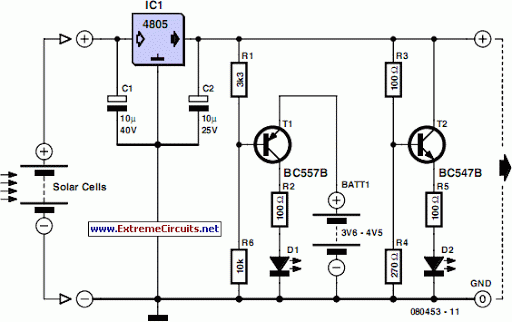
This device is designed to serve as a simple and cost-effective comparator, intended for use in a solar cell power supply system where a quick indication of either too low or acceptable voltage is required. The circuit includes one...
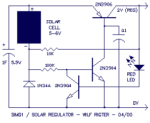
The SIMD1 was enhanced in the Solar Regulator version which supplies a constant 2V after triggering and permits driving LEDs without using current limiting resistors with constant brightness. Note that you can use this Low Drop Out (LDO) linear...
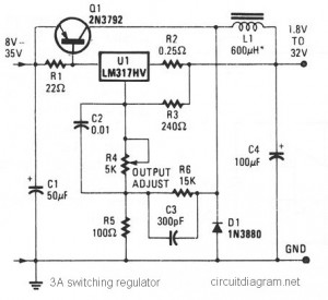
The circuit diagram presented is a simple and cost-effective switching voltage regulator capable of delivering an adjustable output voltage range from 1.8V to 32V with a maximum static current of 3A. This regulator utilizes the adjustable LM317HV IC along...
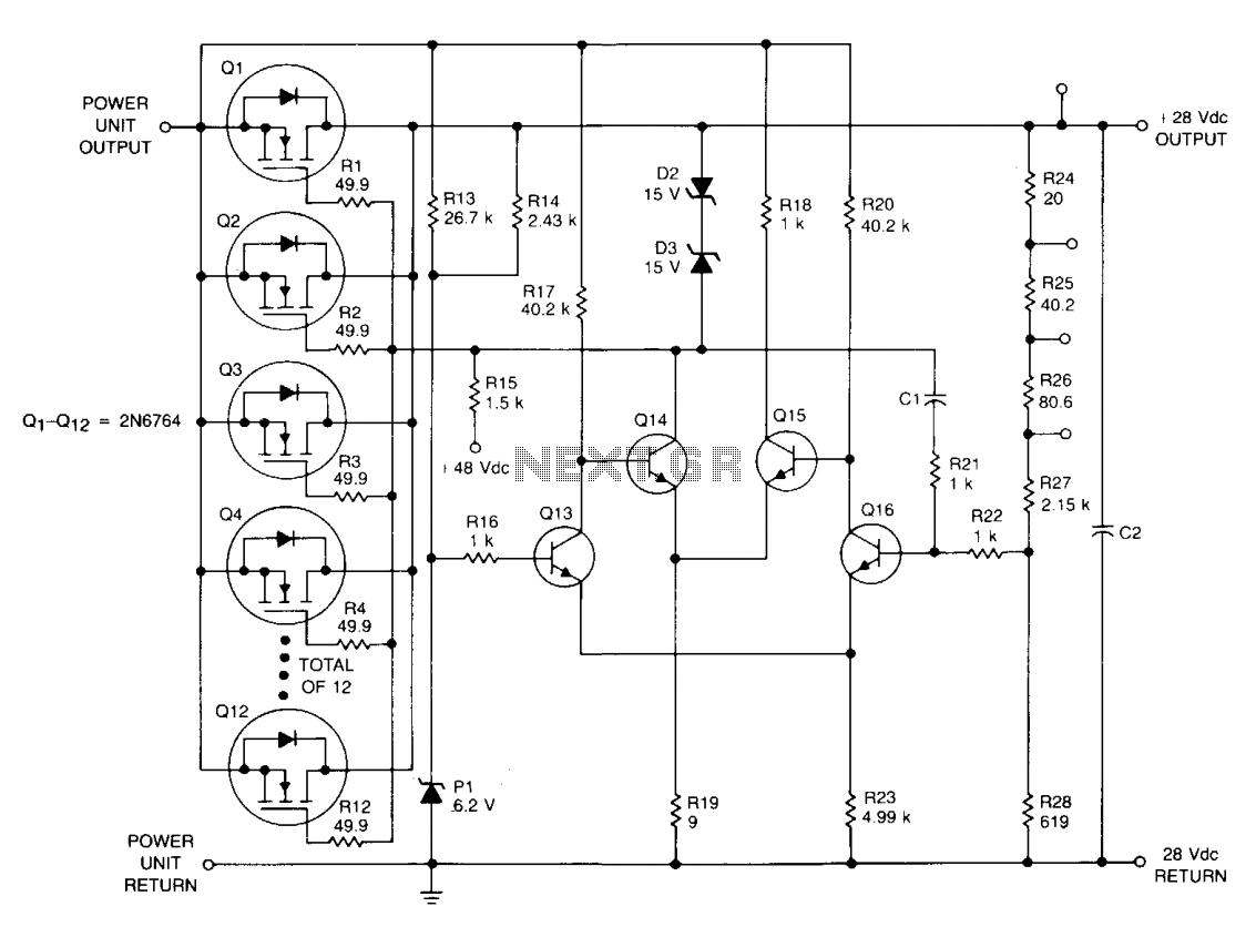
Designed for extreme temperature and radiation-hardened environments, this linear power supply can deliver 28 Vdc at 125 A from an AC-driven power unit. During operation, the output voltage of the power supply is monitored using a voltage divider formed...
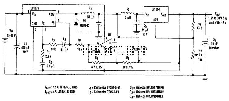
Large input-to-output voltage differentials, caused by wide input voltage variations, reduce a linear regulator's efficiency and increase its power dissipation. A switching preregulator can reduce this power dissipation by minimizing the voltage drop across an adjustable linear regulator to...
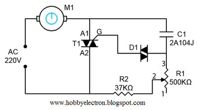
This is a simple ceiling fan regulator circuit diagram used to control the speed of a ceiling fan. In other words, it is an AC motor speed controller circuit that regulates the speed of an AC motor (Ceiling Fan)....