
ceiling fan regulator motor speed

The ceiling fan regulator circuit operates by utilizing the Z0607 TRIAC, which functions as a switch that can control the power supplied to the fan motor. The TRIAC is triggered by the variable resistor (R1), allowing for precise adjustment of the phase angle of the AC supply voltage. This phase control method effectively reduces the average voltage supplied to the fan, thereby controlling its speed.
The variable resistor (R1) is crucial for this application, as it enables the user to select the desired speed of the fan. By adjusting R1, the firing angle of the TRIAC can be modified, which in turn affects the amount of power delivered to the motor. The higher the resistance set on R1, the later the TRIAC is triggered in the AC cycle, resulting in a lower average voltage and reduced fan speed.
Capacitor C1 (2A104J) plays a significant role in filtering and stabilizing the circuit. It helps to smooth out voltage fluctuations and can also influence the timing characteristics of the TRIAC's triggering. The capacitor's value and type are selected to ensure reliable operation and to mitigate any electrical noise that may affect the performance of the circuit.
Overall, this ceiling fan regulator circuit is a straightforward yet effective solution for controlling the speed of ceiling fans, making it suitable for various applications where adjustable fan speed is required. The simplicity of the design, combined with the use of readily available components, makes it an accessible project for both amateur and professional electronics enthusiasts.This is a simple ceiling fan regulator circuit diagram. It is used to control the speed of a ceiling fan. In the other words it is an AC motor speed controller circuit, as because it`s control the speed of a AC motor(Ceiling Fan). This ceiling fan regulator circuit built with few numbers of parts. The circuit mainly based on Z0607 TRIAC. This is a low power AC semiconductor device. Generally which is used to controlling speed of low power ac motor speed. In this ceiling fan regulator circuit, R1=500K is a variable resistor that is used to adjust the fan speed. Capacitor C1 2A104J is a Polyester film capacitor. 🔗 External reference
Related Circuits
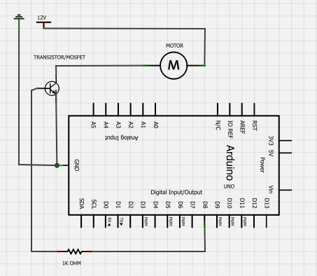
The BC547 transistor has a maximum operating current of 100 mA and a maximum voltage rating of 65 volts. When oriented with the label facing the viewer, the three terminals from left to right are collector, base, and emitter....
A current regulator functions as a load when connected to a voltage source or in series between a voltage source and an actual load. The primary characteristic of a current regulator is to maintain a constant current output regardless...
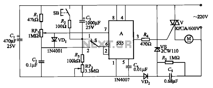
The circuit illustrated in Figure 3-12 incorporates variable speed and timing control functions. When switch S is set to position 1 and button SB is pressed, the motor initiates operation. After a predetermined delay, the motor automatically shuts down....
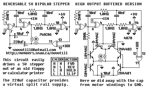
The circuit is not particularly susceptible to motor transients and supports FULL STEPS FORWARD, FULL STEPS REVERSE, ACTIVE HOLD, and POWER OFF aka RELEASED. If the motor does not turn then swap around the leads of ONE of the...
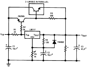
The following circuit diagram illustrates the application of the LM117 as a high current adjustable regulator. The LM117 is capable of supplying more than 1.5A. The LM117 is a popular adjustable voltage regulator that is designed to provide a stable...
This is a reverse-engineered circuit diagram of a one-transistor circuit commonly used to drive permanent magnet DC motors in children's toys. This circuit typically employs the 625mW version of the widely used 8050 or 8550 transistor. It is important...