
ldr engineer

The LDR engineering circuits utilize the fundamental properties of light dependent resistors to create versatile electronic devices. The core mechanism of these circuits relies on the variation of resistance in response to light intensity, allowing the construction of sensors that react to environmental changes. The monostable configuration of the 555 timer in the dark sensor circuit is crucial for timing applications, enabling the LED to remain illuminated for a specified duration, which can be adjusted by changing the values of R1 and C1.
The transition from a dark sensor to a touch sensor is a practical demonstration of how circuit components can be repurposed. The use of a wire in place of the LDR illustrates adaptability in circuit design, allowing for user interaction through touch. This aspect of LDR engineering emphasizes the importance of understanding the underlying principles of electronic components and how they can be manipulated to achieve different functionalities.
The two-transistor dark sensor circuit exemplifies the use of transistors in sensing applications. The interaction between Q1 and Q2 showcases a fundamental principle of electronic circuits: the ability to control one component through another. This principle is critical in various applications, from simple sensors to complex automation systems.
The clap switch design integrates audio sensing through a condenser microphone, broadening the application of LDR engineering concepts. This feature highlights the versatility of the technology and its potential for innovative applications in user interfaces and automation.
Overall, LDR engineering provides a foundation for understanding and creating a wide array of electronic circuits. The principles discussed can be applied to numerous projects, encouraging experimentation and innovation in the field of electronics.LDR( Light dependent resistor ) Engineering is a technique of making several electronics circuits following thelogic of a simple light and dark sensor using transistors, 555 IC and 741 IC. Out of several optical sensors, light dependent resistor can beused for making light/dark sensors. A dark sensor switches on transistor or LED wheneverthe incid ent light intensity is decreased, whereasa light sensor works in opposite way. In LDREngineering, we first understand the working principle of any circuit using LDR, and then we replace the LDRwith a fixed resistor or some other electronic component that makes the simple automatic light/dark sensor work as a completely different device. Making automatic light/dark sensor circuits using different methods can make you observe several electronics components.
On the other hand, modifying those automatic light/dark sensor circuits to some functionally different circuits like touch switch, water level indicator, clap switch, etc. can make you understand about those circuits. In this article, we will see how we can use the concept of a dark sensor to make a touch and a clap switch.
Light dependent resistor (LDR), also called as Cadmium Sulphide (CdS) cell or photoresistoris a resistor whose value depends upon the incident light intensity. In darkness, the resistance ofLDRbecomes high and in light, the resistance gets low. The resistance variation phenomenon of LDRhas been takenas a base for making circuits of LDR Engineering.
The following circuit works as a dark sensor. If the light falling on LDRis blocked, it switches on the LED D1. It has been configuredin monostablemode of 555 timer which means that the circuit switches on the LED D1for a specific time. The switching time is determined by thecombination of resistance R1and capacitor C1. We can make the previous dark sensor circuit work as a touch sensor by making small changes in the schematic.
We just need to remove the LDR, put a small wire and connect it to the coupling capacitor. Note that the electrode wire connected to capacitor C2should bearound 2-5cmlong. As we touch on the wire, the circuit triggers the LED for a specific time as determined by the resistor R1and capacitor C1. You can connect the wire to a small metallic touch plate using an alligator clip. Here, we have another dark sensor that works with two transistors. When light falls on LDR, its low resistance drives transistor Q1-BC547into conduction. This keeps transistor Q2 cut-off due to low basebias. The LED D1does not get power as long as ambient light falls on LDR. When the resistance ofLDR becomes high in darkness, transistor Q1 stops conducting and transistor Q2 starts conducting to turn on the LED.
In order to make a clap switch, we have to combine the previous touch sensor and the transistorizeddark sensor circuits. We also need to connect a condenser microphone in place of LDRand the collector of Q2 has to beconnected to the terminal of capacitor C2.
Whenever there is loud sound produced near the condenser mic, pin 2 of 555 gets triggered and it switches on the LED D1. We can adjust the sensitivity ofthe circuit using a variable resistor in place of fixed resistor R5. If we follow the schematic of figure 6, we can convert the two transistor dark sensor to single transistor light sensor by removing R2, D1and Q2.
The circuit works as a light sensor which switches off the LED wheneverlight falling on LDRis blocked. Now, the light sensor can beeasily converted to a simple water level indicator. We just need to remove the LDR, and dip the wires into water. When both wires are dipped, the circuit switches on the LED D1. We can use copper electrodes for better performance, but for normal experiment, we don`t need any electrode.
VR1-470Kis for adjusting the sensitivity of the circuit. The experiments given in this article have been testedand verified. We can make several other circuits using the idea of da 🔗 External reference
Related Circuits

Approximately one month ago, an attempt was made to reverse engineer a low-cost LED color-changing light bulb. With assistance, the circuit has been mapped out, and control over the bulb has been established. However, several aspects of this device...
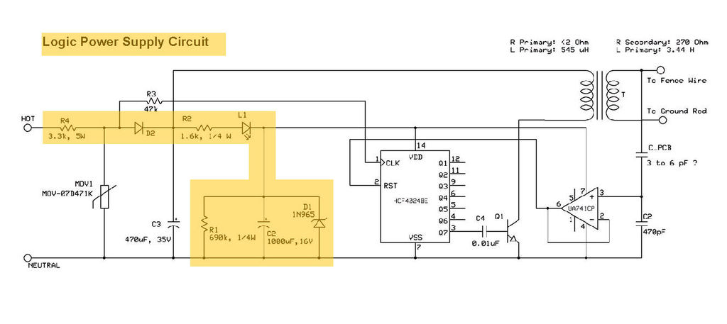
This product includes logic circuitry utilized to control the timing of the output pulses, which will be discussed in a later step. The product features a logic circuit that is integral to managing the timing of output pulses. This...
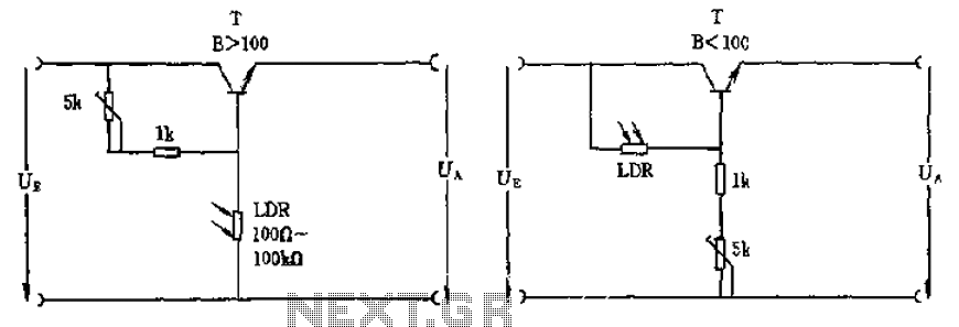
The circuit depicted involves a photoresistor (LDR) connected to a transistor, which operates at either a high or low level based on light conditions. The amplification factor of the transistor is 100, which is adequate for the application. The...
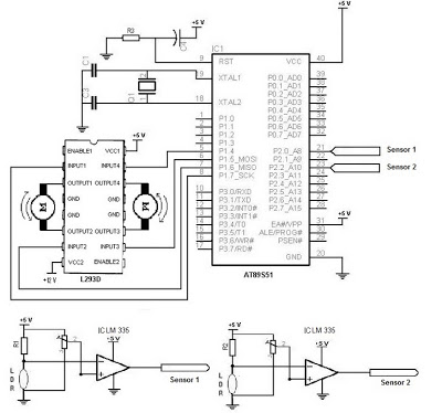
The electronic schematic of the Light Detector Robot can be divided into three main components: the sensor, the microcontroller, and the DC motor driver. The light sensor utilized in this design is a Light Dependent Resistor (LDR), which alters...
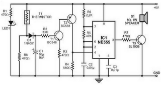
Fire alarm circuit using an LDR (Light Dependent Resistor) as a flame sensor. It warns the user about fire accidents by detecting smoke produced during a fire. As smoke passes between an LED and an LDR, the amount of...
This document describes a simple fire alarm circuit utilizing a Light Dependent Resistor (LDR) and lamp combination for fire detection. The alarm activates by detecting smoke generated during a fire. When smoke is present, the circuit triggers an audible...