
Lead Acid Battery Charger 1
This battery charger circuit is designed to provide a reliable and efficient method for maintaining the charge of a 12-Volt Lead-Acid battery. The core component, the LM350 IC, is capable of delivering adjustable output voltage, making it versatile for various applications. The inclusion of a temperature sensor allows for dynamic voltage adjustment based on the thermal characteristics of the battery, thereby enhancing battery life and performance.
The circuit's design ensures that the output voltage remains within a specified range, adjustable through the potentiometer P1, which allows for fine-tuning based on the specific requirements of the battery being charged. The use of a power diode (D1) safeguards against reverse current flow, which could potentially damage the circuit or the battery. The configuration of resistors R1 and R4, along with the potentiometer, establishes a feedback loop that ensures stability in the charging process.
The temperature compensation feature is critical in preventing overcharging, especially in varying environmental conditions. As the ambient temperature rises, the voltage output decreases, which is essential for maintaining the health of the battery. The recommendation to attach a cooling rib to the transistor Q1 is a prudent measure, as it minimizes the risk of thermal runaway that can occur due to self-heating.
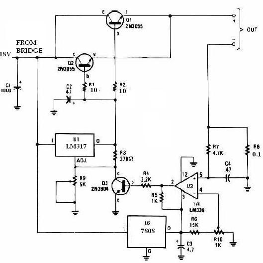
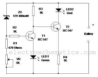
Overall, this circuit is suitable for hobbyists and professionals who require a dependable method to keep their Lead-Acid batteries in peak condition, particularly in applications where battery performance is crucial, such as in remote control systems or other battery-powered devices.Except for use as a normal Battery Charger, this circuit is perfect to `constant-charge` a 12-Volt Lead-Acid Battery, like the one in your flight box, and keep it in optimum charged condition. This circuit is not recommended for GEL-TYPE batteries since it draws to much current. The above circuit is a precision voltage source, and contains a tempe rature sensor with a negative temperature co »ficient. Meaning, whenever the surrounding or battery temperature increases the voltage will automatically decrease. Temperature co »ficient for this circuit is -8mV per °Celcius. A normal transistor (Q1) is used as a temperature sensor. This Battery Charger is centered around the LM350 integrated, 3-amp, adjustable stabilizer IC. Output voltage can be adjusted with P1 between 13. 5 and 14. 5 volt. T2 was added to prevent battery discharge via R1 if no power present. P1 can adjust the output voltage between 13. 5 and 14. 5 volts. R4`s value can be adjusted to accommodate a bit larger or smaller window. D1 is a large power-diode, 100V PRV @ 3 amp. Bigger is best but I don`t recommend going smaller. The LM350`s `adjust` pin will try to keep the voltage drop between its pin and the output pin at a constant value of 1.
25V. So there is a constant current flow through R1. Q1 act here as a temperature sensor with the help of components P1/R3/R4 who more or less control the base of Q1. Since the emitter/base connection of Q1, just like any other semiconductor, contains a temperature co »ficient of -2mV/ °C, the output voltage will also show a negative temperature co »ficient.
That one is only a factor of 4 larger, because of the variation of the emitter/basis of Q1 multiplied by the division factor of P1/R3/R4. Which results in approximately -8mV/ °C. To prevent that sensor Q1 is warmed up by its own current draw, I recommend adding a cooling rib of sorts.
(If you wish to compensate for the battery-temperature itself, then Q1 should be mounted as close on the battery as possible) The red led (D2) indicates the presence of input power. Depending on what type of transistor you use for Q1, the pads on the circuit board may not fit exactly (in case of the BD140).
🔗 External reference
Related Circuits
This universal battery charger utilizes the LM317 voltage regulator and features an adjustable output voltage along with a constant-current charging circuit, making it suitable for charging most NiCad batteries and various other battery types. The LM317 universal battery charger...
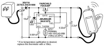
The diagram illustrates a Lithium-ion (Li-ion) battery charger designed using the MAX1879 single chip. This charger offers a simple and cost-effective solution for charging single-cell Li+ batteries without generating heat. The MAX1879, when paired with an AC linear transformer...
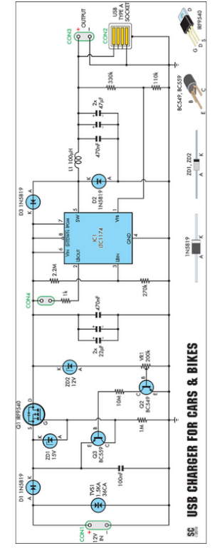
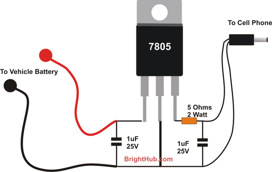
Seeking an efficient USB charger capable of operating from a 12V car battery? This unit operates at up to 89% efficiency and can charge USB devices effectively. This USB charger circuit is designed to convert a 12V car battery supply...
The circuit was constructed on a Vero board and tested with a large electrolytic capacitor in place of a battery. A 500-ohm preset resistor determines the output voltage, while a 47k preset resistor regulates the hysteresis and establishes the...
This circuit monitors the charging process of a 12 Volt Lead Acid or Tubular battery. The LED status indicates whether the battery is charging and signals when it reaches a full charge. It can be integrated into various battery...
With the advent of modern integrated circuits (ICs), sophisticated circuits today are no longer required to be complex and lengthy. The chips themselves contain most of the intricate circuitry built-in and can independently perform the desired functions. For instance,...