
Lead Acid Battery Charger III
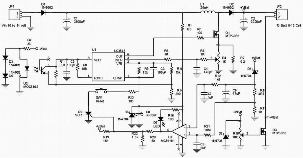
The circuit functions as a battery charger with automatic current regulation and an indicator for full charge. The primary components include the LM350 voltage regulator (U1) and the LM301A operational amplifier (U2). The LM350 is responsible for maintaining the output voltage and requires adequate heat dissipation due to the power it handles. The input voltage is recommended to be around 18 volts to ensure proper operation.
The charging process begins when the pushbutton switch (S1) is engaged, allowing current to flow and the output voltage to rise to 14.5 volts. As the connected battery approaches full charge, the charging current naturally decreases. This is detected by the LM301A, which monitors the current level. Once the current drops below 150mA, the circuit transitions to a float charging mode, reducing the output voltage to approximately 12.5 volts to prevent overcharging.
Resistor R1 serves to bleed a portion of the input voltage, aiding in feedback stability. Resistors R2 and R5, both metal-film types, are used for setting the gain and stability of the op-amp circuit. R2 is configured using two 1.5k ohm resistors in series to achieve a total of 3k ohms, while R5 is formed by two 470-ohm resistors in parallel. R1 can be realized using two 1k ohm resistors in parallel or a combination of 470 ohms and 33 ohms in series to achieve the desired 500-ohm value.
The 0.2-ohm resistor (R7), rated for 5 watts and wire-wound, is critical for accurate current sensing. A ceramic capacitor of 0.1uF should be placed close to the LM301A to filter out high-frequency noise, ensuring stable operation of the op-amp. The visual indicator for a full charge is provided by the LED, which is activated when Q1, a PNP transistor, is biased, signaling that the battery has reached its full charge capacity.
The circuit design is straightforward and adheres to standard electronic symbols, ensuring clarity in implementation and troubleshooting.This high-performance circuit first quickly starts (and holds) the charge at 2 amp, but as the voltage rises the current will consequently decrease. When the current falls below 150mA, the charger automatically switches to a lower 'Float' voltage to prevent overcharging.
At the point that a full charge is reached, Q1 will bias and the LED will light. The LM301A is a 8-pin OpAmp. Transistor Q1 is a PNP, Silicon, AF-Out type with a TO-39 metal case and can be substituted for a NTE or ECG129. Diode D1, a Si, GP Det. type, can be substituted with a NTE177 or ECG177. The LM350 (U1) needs to be cooled. The input voltage should equal or about 18volts. R1's function is to bleed some of the input voltage to the output and vice-versa. A 1N4002 or similar diode can be used also. R2 and R5 are actually metal-film type resistors. To get the 3K for R2 use two 1K5 (1500 ohm) resistors in series. For R5 use two 470 ohm resistors in parallel. Or whatever combination to get to these values. For R1, 500 ohm, you can use two 1K in parallel or 470 + 33 ohms in series. R7, the 0.2 ohm resistor, is a 5 watt wire-wound type. Do not use the standard carbon type. This (optional) 0.1uF (100nF) Ceramic capacitor needs to be mounted over the power lines and as close to the LM301 (U2) S1 is a subminiature pushbutton switch, normally open. I received a couple emails in regards to this switch. When the start switch is pushed, the output of the charger goes to 14.5 V. As the batttery approaches full charge, the charging current decreases and the output voltage is reduced form 14.5V to about 12.5V, terminating the charging process.
Transistor Q1 then lights the led as a visual indication of a full charge. I thought the diagram was pretty clear. It shows an 'open' switch with the arrow indicating a 'momentary' connection when pushed. Nothing out of the ordinary here folks and a standard symbol for electronics. as possible. It will filter off any possible residue hf ripple, which otherwise may prevent this op-amp from working properly. Use only if you have problems with the LM301 not switching off. 🔗 External reference
Related Circuits
Switching to alternative power sources can help reduce electricity bills. The photovoltaic module or solar panel described here is capable of generating renewable energy. The photovoltaic module, commonly known as a solar panel, is a device that converts sunlight into...
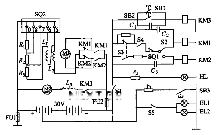
Battery forklifts are commonly used as stacking and handling tools in railway stations, docks, and warehouses. The battery shape and electrical control circuitry are depicted in the schematic. The system consists of batteries connected in series to form a...
The project involves enhancing the Botanicalls system by integrating a solar panel that functions as both a light sensor and a battery charger for each plant. The complete circuit schematic is provided above, along with detailed images illustrating the...
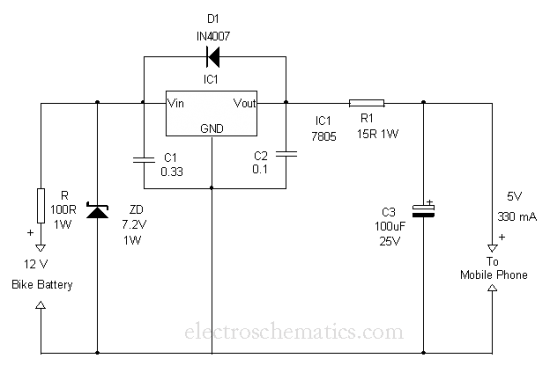
This is a simple and easy method to extract current from a motorcycle battery to charge a mobile phone. Most mobile phone battery packs consist of three 1.2 V cells. To effectively tap current from a motorcycle battery for mobile...
This is a NiMH battery charger using the IC LTC4060, which is powerful, effective, and efficient. The LTC4060 IC specializes in NiMH battery charging, ensuring safe operation with features such as battery temperature protection during charging. It includes a...
The ideas presented here explore various methods for controlling and monitoring the charging of lead-acid storage batteries. To ensure that the benefits of digital technology impact education in developing regions, reliable access during school hours is essential. The O-1.75...