
lead acid battery charger with current limit
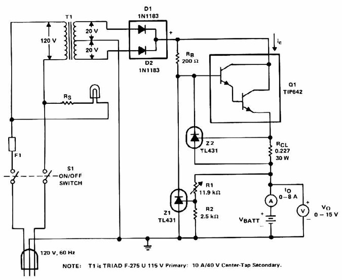
The lead-acid battery charger with a current limit power supply is designed to safely charge lead-acid batteries while preventing overcurrent conditions that could lead to damage. The circuit typically consists of a transformer, rectifier, voltage regulator, and current limiting components.
The transformer steps down the AC voltage from the mains supply to a lower AC voltage suitable for charging the battery. This AC voltage is then converted to DC using a rectifier, which can be either a full-wave or half-wave rectifier configuration, depending on the design requirements.
Following the rectification process, a smoothing capacitor is employed to filter out the ripple voltage, providing a more stable DC output. The voltage regulator is crucial in maintaining a constant output voltage, which is essential for the safe charging of lead-acid batteries. Common voltage regulators include linear regulators or switching regulators, depending on efficiency and thermal management considerations.
To implement current limiting, a resistor or a dedicated current limiting circuit is integrated into the design. This component ensures that the charging current does not exceed a predetermined threshold, protecting the battery from excessive charging currents that could result in overheating or damage.
The circuit may also include additional features such as LEDs for status indication, fuses for overcurrent protection, and thermal shutdown mechanisms to enhance safety and reliability. Overall, this charger design emphasizes efficiency, safety, and adherence to the charging characteristics of lead-acid batteries.Lead Acid Battery Charger with Current Limit power supply. Go to that page to read the explanation about above power supply related circuit diagram. 🔗 External reference
Related Circuits
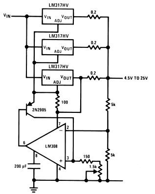
The LM317HV adjustable regulator is capable of supplying over 1.5A across an output voltage range of 1.2V to 57V. The design of this high current power supply is straightforward, as the LM317HV requires only a few external resistors to...
Operating a stepper motor with a fixed (constant) voltage supply leads to inadequate torque at high speeds, often causing the motor to stall at relatively low speeds. To address this issue, various solutions can be implemented, one of which...
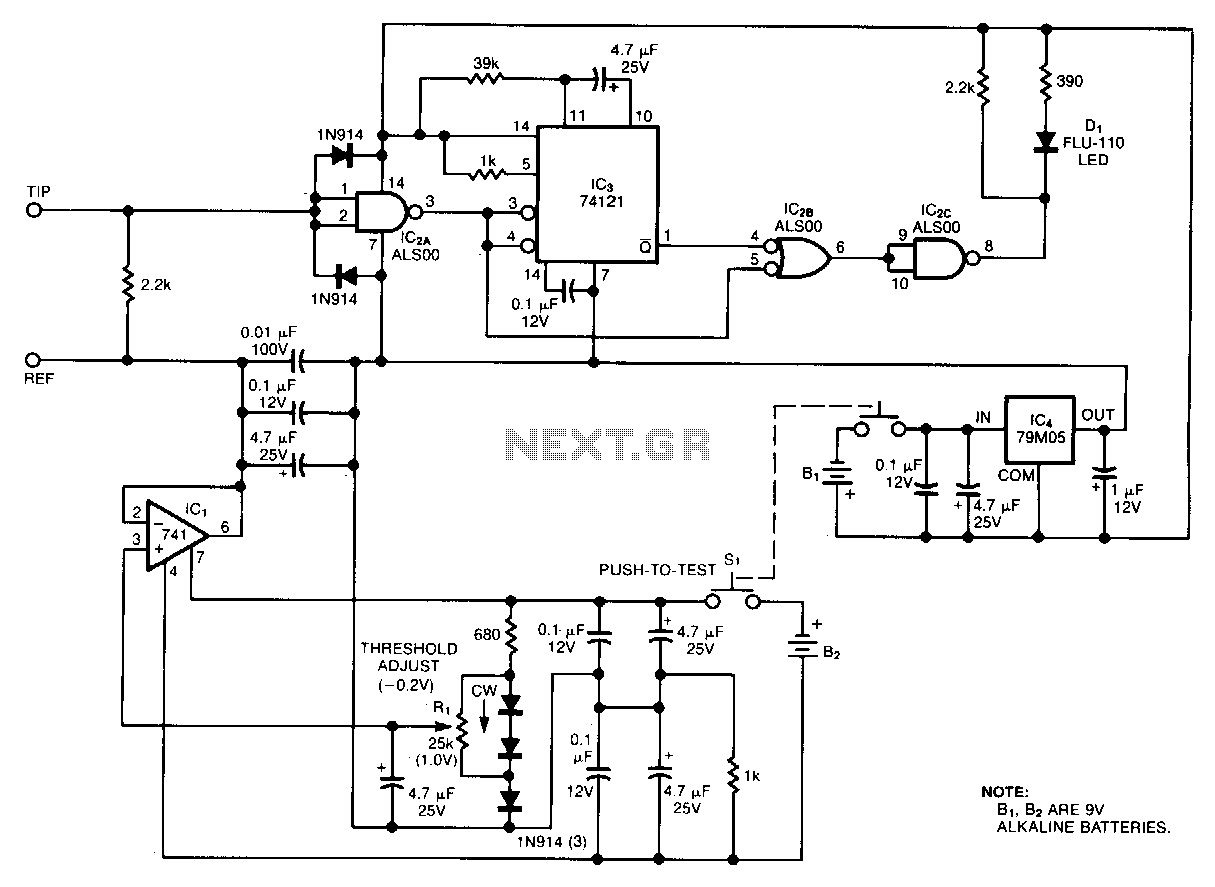
The circuit depicted in the figure consists of a battery, a controller, and various electrical and charging components. It includes a Zener diode (D1) and resistors (R1, R2) for undervoltage detection. The circuit also features transistors (Q1, Q2), resistors...
Oscilloscope measurements of ground noise can be unreliable because noise can enter your circuit via the scope's three-pronged power plug. This issue can be mitigated by utilizing the ground-noise tester described. The circuit operates on two 9-V batteries and...
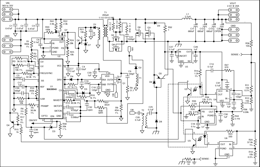
This application note details the design of a 50-watt, isolated, forward converter, utilizing the MAX8540 synchronizable, high-frequency, current-mode PWM controller. The schematic design of the 50-watt isolated forward converter using the MAX8540 involves several key components and stages to ensure...
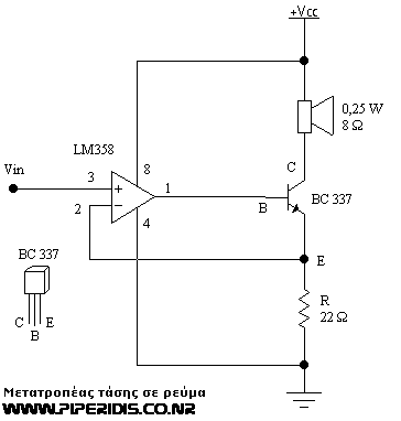
This circuit is one of the simplest voltage-to-current converters designed to drive low loads. In this example, a small 0.25-watt speaker with an 8-ohm resistance is utilized. It is suitable for microcontroller applications or any circuit that employs PWM...
Warning: include(partials/cookie-banner.php): Failed to open stream: Permission denied in /var/www/html/nextgr/view-circuit.php on line 713
Warning: include(): Failed opening 'partials/cookie-banner.php' for inclusion (include_path='.:/usr/share/php') in /var/www/html/nextgr/view-circuit.php on line 713