
Volt To Current
This voltage-to-current converter circuit is characterized by its simplicity and effectiveness in driving low-resistance loads, such as speakers. The primary function of the circuit is to convert a voltage input into a proportional current output, which is essential for efficiently driving devices like speakers that require a specific current to operate optimally.
The circuit typically consists of a voltage input stage that connects to the PWM output from a microcontroller. The PWM signal modulates the duty cycle, effectively controlling the average voltage and, consequently, the current delivered to the load. The use of an 8-ohm speaker in this example highlights its application in audio output scenarios, where precise control over the current is crucial for sound quality.
For analog signal applications, the circuit's design necessitates a power supply that exceeds the highest voltage level of the input signal. This precaution helps to avoid saturation, ensuring that the output remains linear and responsive to the input variations. The choice of power supply voltage is flexible; however, it is essential to maintain stability at 5 volts for consistent performance. Using a 4.5-volt battery or a 9-volt battery is common practice, and the circuit can accommodate even higher voltages, such as 12 volts, provided that the components are rated accordingly.
Component selection is critical in this circuit. The use of a 0.5-watt resistor is recommended over a 22-ohm 1/4-watt resistor to ensure that the resistor can handle the power dissipation without overheating. This consideration is vital for maintaining circuit reliability and longevity.
Overall, this voltage-to-current converter circuit is a versatile solution for driving low-power loads in various applications, including audio systems, PWM-controlled devices, and other microcontroller-based projects. Its straightforward design makes it an excellent choice for engineers seeking an efficient method of signal conversion and load driving.This circuit is one of the simplest voltage to current converters to drive low loads. In this example a small 0, 25 Watts speaker, with 8 © resistance, is driven. It is suitable for microcontroller designs or any other circuit that uses PWM (TTL logic). You can use it for analog signals as well. The circuit is not amplifying the input voltage signa l (use a preamp if it is necessary). For analog signals is better to use a power supply higher than the maximum voltage of the input signal, to avoid saturation effects. For digital signals it is not necessary. Also you will need a stabilized 5 Volt external power supply. You can use a 4. 5 Volt battery or even a 9Volt battery. Higher voltages can also be used (e. g. 12 Volts). Attention: Vcc is the power supply (5 or 9 Volts). You can also use a 4. 5 Volt battery. Do not use a 22 Ohm 1/4 Watt resistor. Use a 0. 5 Watt resistor instead. 🔗 External reference
Related Circuits
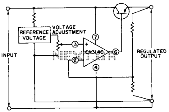
The circuit utilizes a CA3140 BiMOS operational amplifier that is capable of providing a regulated output adjustable from approximately 0 to 24 volts. The circuit is fully regulated. The CA3140 BiMOS operational amplifier is a versatile component that combines the...
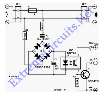
The detector is designed to sense and signal to another circuit when an appliance is connected to the mains voltage. For this purpose, an optocoupler, IC1, is utilized. The circuit employs an optocoupler (IC1) to provide electrical isolation between the...
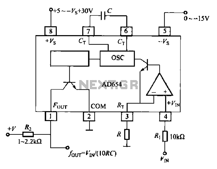
The AD654 voltage-frequency converter is a low-cost device that operates with a single supply voltage ranging from +5V to +36V, as well as with dual supplies of +5V to +18V. It can handle a maximum input voltage of 36V...
Additionally, it may be necessary to include another input capacitor to mitigate high-frequency noise, although this is not directly related to the main question. The objectives are to achieve a voltage output of 0 - 12 V with a...
The current tracer is designed to identify a defective integrated circuit (IC) that is causing excessive loading on the power supply. It amplifies the small voltage drop that occurs due to current flow over a short length of printed...
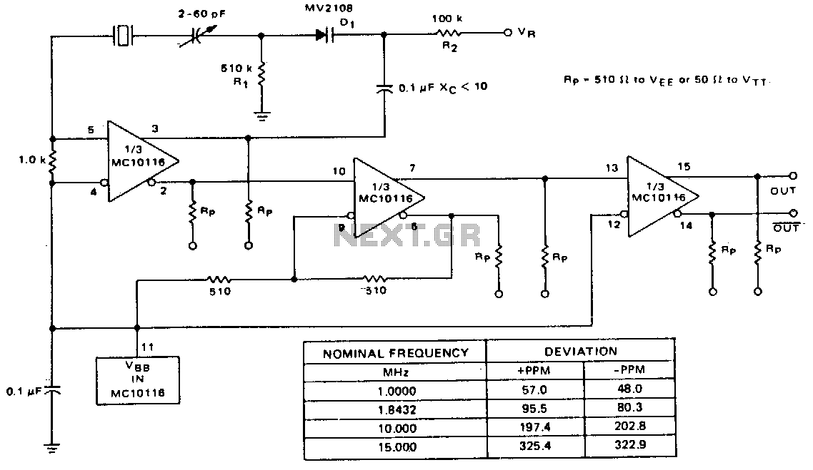
A voltage-variable capacitance tuning diode is connected in series with the crystal feedback path. Adjusting the voltage on the variable resistor (VR) changes the capacitance of the tuning diode, which in turn tunes the oscillator. The 510 kΩ resistor...