
12V battery production controller
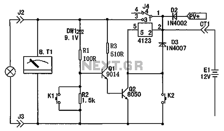
Working Principle: When electricity is required, pressing the button switch (K2) energizes the relay coil, closing contacts (1) and (3) to allow current to flow from the battery to the load. The Zener diode (D1) conducts when the battery voltage exceeds 10.8V, forward-biasing transistors Q1 and Q2, which keeps the relay in a conductive state even after releasing switch K2, thus maintaining circuit operation. To turn off the power, switch K1 is activated, grounding the base of Q1, which synchronously turns off Q1 and Q2, deactivating the relay.
To prevent over-discharge of the battery, the circuit detects when the battery voltage drops below 10.8V. In this case, Zener diode D1 blocks reverse voltage, causing Q1 to turn off and the relay to deactivate, thereby protecting the battery from damage. Component specifications include a 1/8W resistor, a relay (such as 4123 or T73) with a current rating above 5A, an indicator (91L16, 20V voltmeter), and maintenance-free lead-acid batteries rated at 12V 7Ah. The Zener diode (D1) should have a voltage rating between 9.0V and 9.1V to ensure proper operation, as exceeding 10.8V will prevent discharging. Additional component parameters are standard without special requirements. The assembly diagram illustrates the connections, with the positive output terminal (0UT) connected to the battery cathode (V+), and the positive terminals of the solar panels or charger linked to the PV+ input, while the negative terminals are connected to the ground.
This circuit effectively combines automatic and manual control for energy management, ensuring battery longevity and operational efficiency. Circuit shown in FIG. Circuit by the battery, the controller, with electrical and charging parts. Wherein: Zener diode DWl, resistors R1, R2 composition undervoltage detection circuit, transistor Q1, Q2 and the resistors R3 and undervoltage relays automatic power control circuit execution. K1, K2, respectively Manual Off, open button switch machine, PV + solar panels charge the positive input terminal.
Load preferably 1 2V DC electronic energy-saving lamps. working principle: When you needed electricity. Push button switch K2, at this time the relay coil is energized; while relay contact (1) and the contact (3) is closed is turned on, a positive voltage from the battery contacts (1) flow through the contact (3); circuit electrical work. Zener diode D1 when the battery voltage is higher than 10.8V breakdown conduction, transistor Q1, Q2 forward-biased conduction, this time relay maintain captive conductive state, even if the button is released K2, the circuit is still in normal working condition.
When you need to turn off the power, hand-activated shut-off button K1, this time the base of Q1 b ground, Q1, Q2 synchronization off, the relay off, shut off. When the battery voltage is lower than the discharge 10.8V. Should stop discharging to prevent over-discharge damage to the battery. This function is performed by the undervoltage detecting circuit DW1, R1, R2 and execution circuit Q1, Q2, R3, and the relay is completed.
When the battery voltage is lower than 10.8V, DWl reverse blocking, leading to Q1, Q1 is turned off, the relay off, reaching off automatically to protect battery discharge purposes. Components and options: Generating resistor 1/8W, with 4123 or T73 relay contacts and other current is greater than 5A of small electromagnetic relay, indicator selected 91L16,20V voltmeter, battery is maintenance-free lead-acid batteries 12V7Ah Above, DW1 Zener diode voltage requirements value between 9.0-9.1V, otherwise 10.8V overvoltage will not discharge design value.
Other component parameters as shown, no special requirements. Printing and assembly drawing in the following figure, the figure V + of battery cathode, 0UT positive output voltage terminal. PV + connected solar panels (or charger) positive, GND of battery and PV panel (or charger) negative.
Related Circuits
This battery allows the indicator to the car battery voltage monitor. The indicator has four LEDs which indicate power. The more LEDs, the higher the voltage. The last LED is a flashing LED. It comes on when the accuspaning...
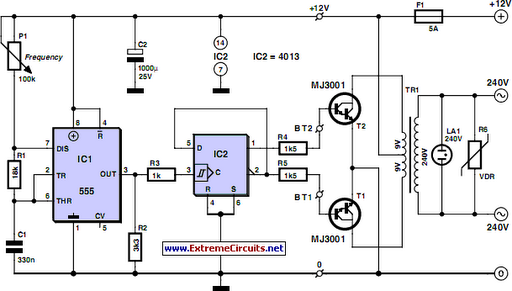
Although today's electrical appliances are increasingly self-powered, especially portable ones used for camping or summer holidays, there are still occasions when a 230 V AC source is necessary. If the power requirement from such a source remains relatively low—here,...
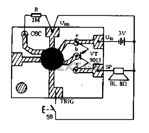
Constantly changing light and sound analog controller circuit 01 The described circuit functions as an analog controller designed to modulate light and sound outputs in a dynamic manner. This circuit typically integrates various electronic components, including resistors, capacitors, transistors, and...
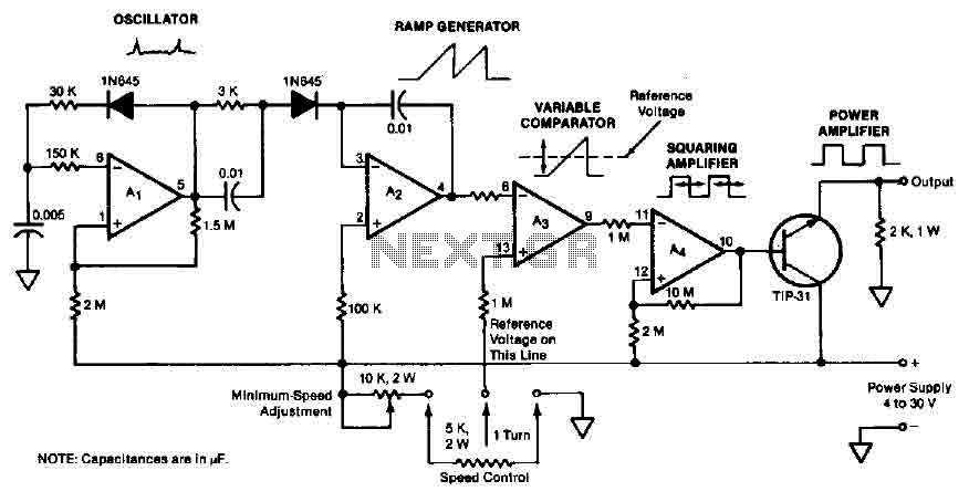
The quad operational amplifier circuit provides a pulse width modulation control ranging from 0 to 100 percent. The controller utilizes an LM3900 and operates with a single supply voltage between 4 to 30 V. A 1 kHz oscillator amplifier,...
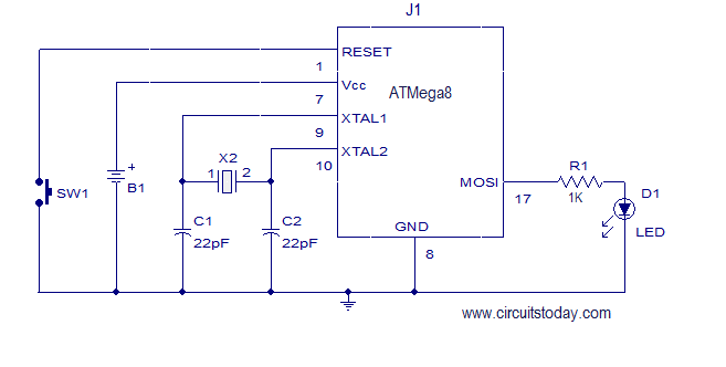
This article explains how to add a 32K external crystal/clock source to the Atmel AVR microcontroller Atmega8, including a circuit diagram and a C program. The Atmel AVR microcontroller Atmega8 is a popular choice for various embedded applications, often requiring...
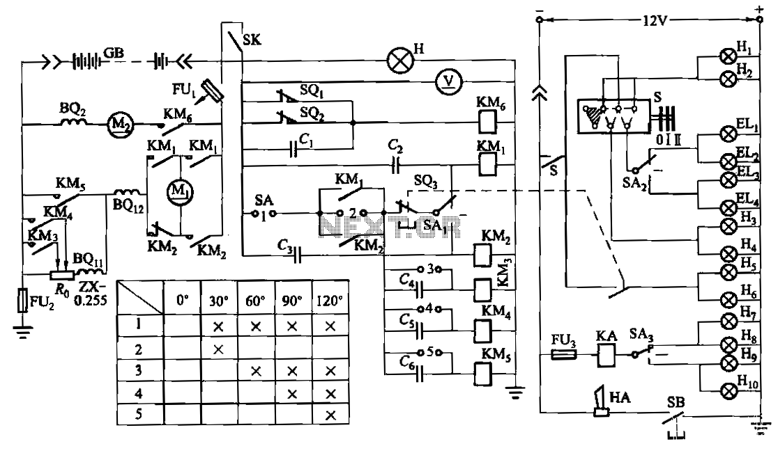
The forklift electric drive system comprises two DC series motors and associated control equipment. A 4.5 kW electric motor drives the vehicle through a mechanical transmission mechanism, enabling forward and backward movement of the forklift. A 6 kW pump...
Warning: include(partials/cookie-banner.php): Failed to open stream: Permission denied in /var/www/html/nextgr/view-circuit.php on line 713
Warning: include(): Failed opening 'partials/cookie-banner.php' for inclusion (include_path='.:/usr/share/php') in /var/www/html/nextgr/view-circuit.php on line 713