
NiCAD Battery Charger with Current and Voltage Limiting
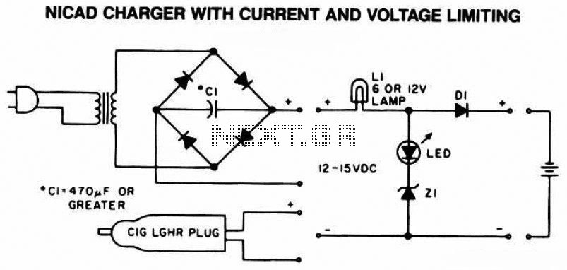
This Ni-CAD battery charger circuit is designed to ensure safe and efficient charging of nickel-cadmium batteries. The key components of the circuit include a transformer, rectifier, voltage regulator, current limiting resistor, and indicator lamps.
The transformer steps down the mains voltage to a suitable level for charging the battery. Following the transformer, a rectifier converts the AC voltage to DC, which is necessary for charging the battery. The rectified output is then smoothed using a capacitor to reduce ripple voltage, providing a more stable charging voltage.
Current and voltage limiting features are critical in preventing overcharging, which can damage the battery and reduce its lifespan. A current limiting resistor is included in the circuit to restrict the maximum current flowing to the battery. Additionally, a voltage regulator may be employed to maintain a consistent output voltage, ensuring that the battery does not exceed its rated voltage during the charging process.
The indicator lamp L1 provides a visual indication of the charging status. When the charger is actively charging the battery, L1 will illuminate brightly, signaling that the circuit is functioning correctly. Conversely, an LED indicator will be off when the battery is fully charged, indicating that charging has ceased to prevent overcharging.
Overall, this schematic diagram presents a comprehensive solution for charging Ni-CAD batteries safely and effectively, extending their operational life through careful management of current and voltage during the charging process.The following diagram is the schematic diagram of Ni-CAD Battery Charger circuit which featured with current and voltage limiting to keep the battery lifetime. The lamp L1 will be light brightly and the LED will be out when the battery is.. 🔗 External reference
Related Circuits
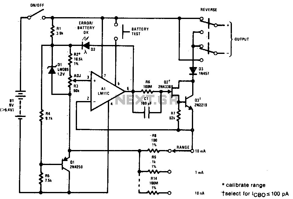
This precision current source features output current ranges from 10 µA to 10 mA, with an output compliance of 30 V to -5 V. The output current is fully adjustable within each range using a calibrated ten-turn potentiometer. An...
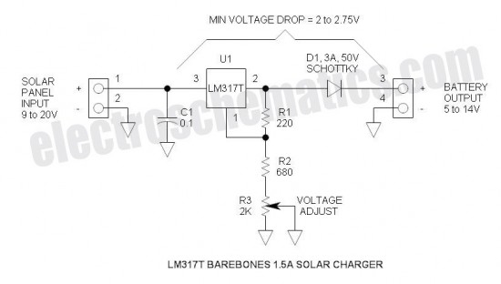
This is a simple and cost-effective solar battery charger that can be constructed by hobbyists. It has some limitations compared to other similar controllers, but it also provides several benefits. While primarily designed for charging lead-acid batteries, it can...
The current loop interface circuit diagram of the AD694 multi-functional sensor signal conditioner is utilized as a digital-to-analog converter (DAC). This current loop interface enables the conversion of digital values into voltage and subsequently into current signals. The circuit...
This is a simple NiCd battery charger powered by solar cells. A solar cell panel or an array of solar cells can charge a battery at more than 80% efficiency, provided the available voltage exceeds the fully charged battery...
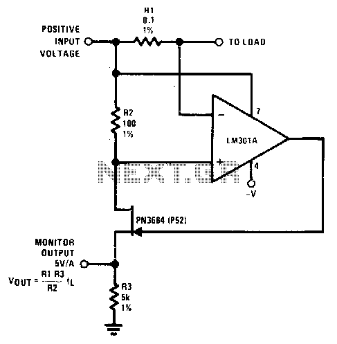
The resistor (Rl) senses the current flow of a power supply. The JFET is utilized as a buffer since Id equals Is; thus, the output monitor voltage accurately represents the current flow of the power supply. In this circuit, Rl...
The Traynor YBA-1 is closely related to the classic Bassman/JTM-45 circuit. A vintage '67 model was acquired, which was in excellent condition except for a poorly executed reversible master volume modification and a burnt power transformer. This version features...