
Lead Acid Battery Discharge protector
This circuit is designed to monitor and protect lead-acid batteries from over-discharge, a condition that can lead to irreversible damage. The system operates by continuously measuring the battery voltage and providing a visual indication through an LED when the voltage falls below a critical threshold of 10.8V. The core component of the circuit is the LM723 voltage regulator, which functions as a voltage comparator in this application.
The circuit is powered by the battery being monitored, with its terminals connected directly to the battery poles. The LM723 is configured to generate a stable reference voltage of approximately +7.15V at pin IC1/6 when the input voltage exceeds +9.5V. This reference voltage is used to compare against the voltage at pin IC1/4, which is derived from the battery voltage and adjusted by a trimmer potentiometer (TR1).
When the voltage at IC1/4 exceeds the reference voltage at IC1/5, the output at IC1/9 goes low, which turns off the transistor Q1, consequently switching off the LED indicator. Conversely, if the voltage at IC1/4 drops below the reference voltage at IC1/6, the output at IC1/9 transitions high, allowing current to flow through Q1 and illuminating the LED. This visual alert informs the user that the battery voltage has fallen to a potentially damaging level.
To ensure proper operation, the circuit requires an external regulated supply that maintains a voltage of at least +10.8V. The trimmer potentiometer TR1 is adjusted to set the precise voltage threshold at which the LED activates, ensuring timely warnings before the battery reaches a critical discharge state. This monitoring circuit is ideal for applications utilizing 12V lead-acid batteries, providing a simple yet effective solution for battery management and protection.In perfect discharge the batteries of lead acid, exists the fear they are destroyed. This circuit makes the work, this detection of discharge, protecting the batteries from destruction. At the discharge the polar voltage of batteries 12V of Lead acid, is not allowed it is decreased under 10.8V, thus we have warning with the turn on of Led, when the voltage falls under this price. In order to we achieve the control, we needed a stability voltage and a circuit that could him compare with the checked voltage.
And two these condition provide to IC1- LM 723. The terminal entry of circuit they are connected in the poles of battery. In the IC1/6 is presented a stability voltage + 7.15V, when the voltage of entry is bigger than + 9.5V. The stability voltage is applied in the IC1/5. In the IC1/4 is applied a part of voltage of entry, that is checked by the trimmer TR1. The IC1 is as voltage comparator. Thus when the voltage in the IC1/4 is bigger than the voltage in the IC1/5, then the exit of IC1/9, has low level [ L ], the Q1 is in cutting off and the LED it is off.
In order to it turns on the LED should the voltage in the IC1/4 become smaller than the voltage of reference in the IC1/6, whenever the exit of IC1/9 will become high [ H ], Q1 conduct and the LED turn on. For the regulation of circuit we will need exterior supply, which is regulated has expense + 10.8V, him applies in the entry of him circuit.
We regulate the trimmer TR1, so as to it turns on LED,me the least alleviation of voltage from supply. The terminal entry of circuit, it should they are connected directly in the poles of battery, it can be used where we use batteries 12V of (Lead acid).
🔗 External reference
Related Circuits
The Over-the-Top type of operational amplifier is ideal for use as a current sensor for battery charger applications. The design described here can be used with chargers for rechargeable batteries (Lead/acid or NiCd, etc.). The 5 V operating supply...
The device serves to quickly establish the status of an indicative power cells. I built it for his children, so they can determine the degree of self-discharge batteries in a variety of toys. WAS tester designed to test the...
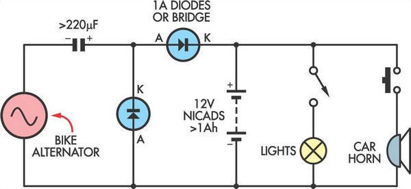
This simple circuit enables a 12V battery pack to be charged using a bike generator. The generator is rated at 3W and, with the inclusion of a voltage multiplier circuit, delivers approximately 200mA at a speed of around 15...
This project originated from the need for a Li-ion charging circuit that offers more flexibility than typical do-it-yourself circuits while being more affordable than programmable computerized chargers. The primary objective was to design, build, test, and share a charger...

This circuit utilizes a pair of Zener diodes to monitor the voltage of a 12-V battery. When the voltage drops below 11 V, diode D1 ceases to conduct, causing pin 3 of flip-flop IC2 to go high. This action...
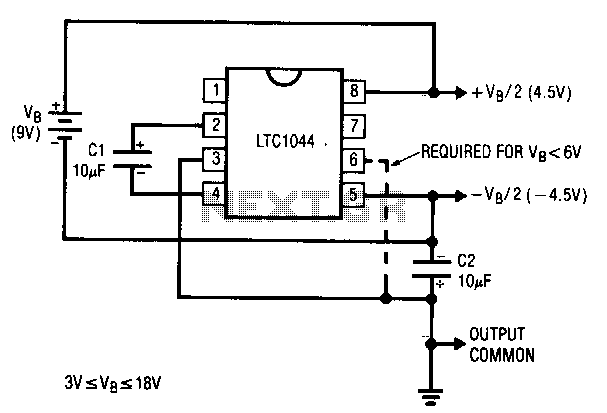
A common requirement in many systems is to obtain both positive and negative supplies from a single battery. For applications with small current needs, the circuit illustrated provides a straightforward solution. It generates symmetrical output voltages of ±, each...