
Battery Charger Display Using LT1639
The operational amplifier circuit described is tailored for monitoring the current flow in battery charging applications, specifically targeting rechargeable batteries such as lead-acid and nickel-cadmium types. The circuit operates on a 5 V supply derived from the battery under charge, which ensures that the system is self-sufficient during operation.
The sense resistor R8 is a critical component that allows the circuit to accurately measure the current. By placing this resistor in series with the battery, the voltage drop across R8 can be correlated to the current flowing in or out of the battery, thanks to Ohm's Law (V = IR). The LED indicator provides a visual cue regarding the charging state of the battery, illuminating when current is flowing into the battery and extinguishing when it is discharging.
The dual operational amplifier configuration (IC1a and IC1b) forms the basis for a current sensing mechanism, where each op-amp is dedicated to one of the two states: charging or discharging. The transistors T1 and T2 act as current sources, ensuring that the appropriate op-amp is activated based on the current direction. When discharging, IC1a and T1 work together to provide a proportional output voltage across R5, which is directly related to the current sensed through R8. Conversely, during charging, IC1b and T2 take over, maintaining the same proportional relationship.
Amplification of the sensed voltage is achieved through IC1d, which is configured to provide a gain of 10 under standard conditions. This means that a current of 0.1 A results in a measurable output of 1 V, allowing for easy interpretation of the current levels. For applications requiring a display of higher currents, modifications can be made by omitting resistor R7 or adjusting the value of R8, thereby altering the gain and scaling the output voltage accordingly.
The design also emphasizes the importance of the supply voltage to the operational amplifiers, which must exceed the operational voltage for proper functionality. The LT1639 operational amplifier can handle a wide range of supply voltages, allowing for flexibility in various applications. The circuit is designed to handle input voltages significantly above the supply voltage, ensuring robust performance even in fluctuating conditions.
In summary, this operational amplifier circuit provides a reliable and efficient means of monitoring battery charging and discharging currents, with the capability to adapt to different battery types and capacities. The integration of visual indicators and analog outputs enhances usability, making it suitable for a range of battery management applications.The Over-the-Top type of operational amplifier is ideal for use as a current sense for battery charger applications. The design described here can be used with chargers for rechargeable batteries (Lead/acid or NiCd etc).
The 5 V operating supply for the circuit is derived from the battery on charge. The circuit uses a sense resistor R8 to determin e the value of current‚owing in or out of the battery. An LED output shows whether the battery is charging or discharging and an analogue output displays the battery charge or discharge current. The circuit can also be altered to shown different ranges of charging current to cater for higher capacity cells.
IC1a and IC1b together with T1 and T2 form two current sources, which produce a voltage across R5. The voltage across R5 is proportional to the current through resistors R8 and R1 (for IC1a) or R8-R3 (for IC1b). The current source formed by IC1a and T1 is active when the batteries are discharging and IC1b and T2 is active when the batteries are being charged.
In each case the inactive opamp will have 0V at its output and the corresponding transistor will be switched off. IC1d amplifies the voltage across R5, which is proportional to the sense current. The component values given in the diagram produce an amplification factor or 10. A sense current of 0. 1 A will produce an output voltage of +1 V. The supply voltage to the circuit is +5 V so this will be the maximum value that the output can achieve.
This corresponds to a maximum charge/discharge current of 0. 5 A To display currents from 0 to 5. 0 A, resistor R7 can be omitted to give IC1d a voltage gain of 1. Higher currents can be displayed by using a lower value of sense resistor R8. A DVM or analogue meter can be used at Vout to give a display of the charge/discharge current. The constant current sources can only function correctly when the supply to the voltage regulator circuit (UBatt. e. g. 6V or 12V) is greater than the operating voltage of the opamps (+5 V). The supply voltage to the LT1639 can be in the range of +3 V and +44V and voltages up to 40V over the supply voltage are acceptable at the inputs to the opamp.
IC1c controls the charging/discharging LED output. The inputs to this opamp are connected to the outputs of the current source opamps and its output goes high when the battery is being charged and low when it is discharging. 🔗 External reference
Related Circuits

The circuit is designed to connect in parallel with a telephone, displaying the dialed number using DTMF (Dual Tone Multi-Frequency) signaling. It can also show the number dialed from the receiving party's phone, making it useful for capturing numbers...
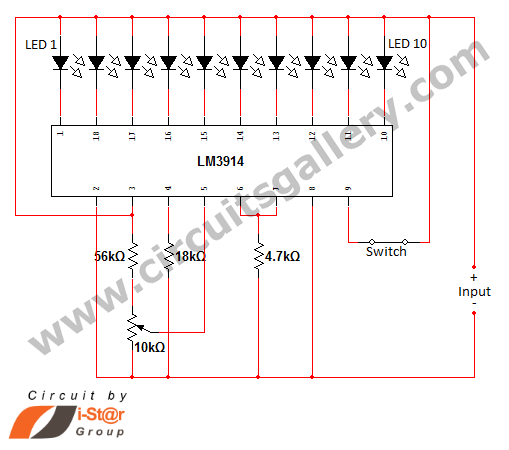
In various situations, it is necessary to indicate the amount of battery charge using methods such as LED dot displays or LED bar displays. This circuit utilizes the LM3914 integrated circuit to serve as a battery charge indicator with...
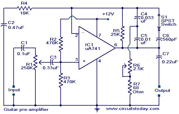
A preamplifier circuit designed for high-impedance electric guitar pickups is presented. This circuit utilizes a uA 741 operational amplifier (IC1) configured as a non-inverting amplifier. The potentiometer R1 functions as a volume control, while potentiometer R6 serves as a...
Here is a simple technique for measuring frequencies over quite a wide frequency range and with acceptable accuracy limits using a PC. It follows the basic technique of measuring low frequencies, i.e. at low frequency, period is measured for...
The object is to get the cell voltage high enough for the sulphate to dissolve without boiling or melting the battery. This is achieved by applying higher voltage for shorter periods and let the battery rest for a while....
This 3A charger was originally designed to work with small batteries like those used in motorcycles. In principle it can be used to charge car batteries also but will take a lot longer. The charger below charges a battery...
Warning: include(partials/cookie-banner.php): Failed to open stream: Permission denied in /var/www/html/nextgr/view-circuit.php on line 713
Warning: include(): Failed opening 'partials/cookie-banner.php' for inclusion (include_path='.:/usr/share/php') in /var/www/html/nextgr/view-circuit.php on line 713