
LED TesterCircuit
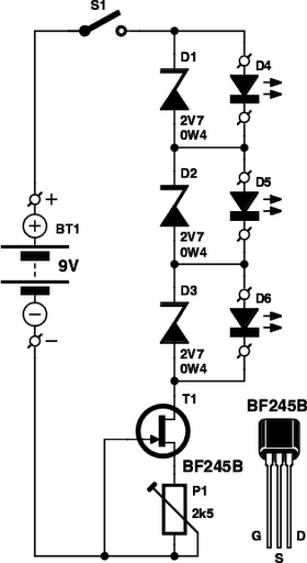
The LED tester circuit is designed with simplicity and functionality in mind, allowing for the testing of multiple LEDs simultaneously while ensuring reliable operation even when faced with defective components. The use of a constant-current source through FET T1 is pivotal in maintaining consistent brightness across the tested LEDs, which is crucial for applications requiring uniformity in lighting. The inclusion of Zener diodes not only protects the circuit from potential damage due to incorrect LED polarity but also enhances the testing capability, making it versatile for various LED types. The adjustment feature provided by potentiometer P1 allows for fine-tuning of the current, accommodating different LED specifications and ensuring optimal performance.
Furthermore, the circuit's adaptability to different LED types, including the requirement for higher forward voltages for modern LEDs, underscores its practicality for hobbyists and professionals alike. The ability to use standard components such as IC sockets facilitates ease of use and maintenance, making this LED tester an invaluable tool in electronic projects involving LED displays or indicators. Overall, this LED tester circuit exemplifies an effective solution for ensuring the reliability and functionality of LEDs in various applications.You have to admit that these tiny electronic lamps are handy, and they last almost forever. Around 40 years after Nick Holanyak developed the first LED, they have become just about indispensable. Any self-respecting electronics hobbyist always has a few in his junk box. But before you use LEDs, it`s a good idea to check them out. With a LED tester , you can even do it in the dark! LEDs are available nowadays in all shapes and colors. There are types with clear, colorless packages, while others have colored plastic packages. Many modern types of LEDs need less current than older types. Some of them provide quite a puddle of light if you give them a decent amount of current. When you`re working with used LEDs from the junk box, there`s a good chance that you can`t tell which lead is which any more. (If the leads haven`t been trimmed, the short lead is always the cathode lead and the long lead is the anode lead.
) If you use several LEDs in a display where they all have the same current you naturally want all the LEDs to have the same brightness. But that`s not always the case, even with LEDs of the same type. To save yourself unnecessary soldering work, it`s a good idea to check the LEDs out first. That`s the job of the LED tester described here. This circuit can be used to test up to three LEDs at once, connected in series. You can easily increase that number by using a higher supply voltage. If you do so, you should allow 2. 7 V for each additional LED. The Zener diodes are included in the circuit so it can also be used to test one or two LEDs. Another benefit of the Zeners is that even if one or more of the LEDs are defective or connected with reverse polarity, the remaining ones will light up normally.
That makes it easy to spot suspect LEDs. If you extend the tester to handle more LEDs, you must add another Zener diode for each LED position. The test current that ows through the LEDs is held reasonably constant by FET T1, independent of the number of LEDs being tested.
The FET is used as a constant-current source to keep the circuit as simple as possible. The drawback of this approach is that the tolerance range of FET characteristics is especially large. The type used here even has three versions: A, B and C. We used the B version here so the current through the LEDs can be adjusted using potentiometer P1 over the range of 1 7 mA.
If you need more current, you can use a BF254C instead, but then you will also need a higher supply voltage. For example, you can connect two 9-V batteries in series or power the circuit from a mains adapter. However, some LEDs have a maximum rated current of only 5 mA. You should thus always start testing at the lowest current by setting P1 to maximum resistance. You can easily see from the brightness whether you need more current. If an LED does not light up, it may be defective or connected the wrong way round. Reduce the current to the minimum level before reversing or replacing any LEDs. If you label the polarity of the terminals on the LED tester, you can easily mark the cathode and anode leads of the tested LEDs.
To make it easy to swap the LEDs, you can use an IC socket as a test socket. The selected Zener diodes were chosen to make the tester suitable for red, yellow and green LEDs. Red LEDs have a forward voltage of 1. 6 V to 1. 8 V. The value for yellow LEDs is around 1. 9 V, and with green LEDs the forward voltage can be as high as 2 V. If you also want to test modern blue or white LEDs, you will have to replace the Zener diodes with types having a voltage of 4. 7 V or 5. 1 V. The supply voltage will also have to be increased accordingly for example, by connecting two 9-V batteries in series.
🔗 External reference
Related Circuits
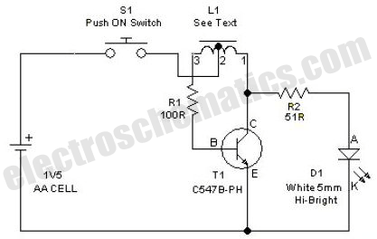
This simple LED driver circuit allows the operation of up to seven LEDs using a single NiMH (Nickel Metal Hydride) AA cell. The circuit generates voltage pulses. The LED driver circuit is designed to efficiently power multiple LEDs while maintaining...
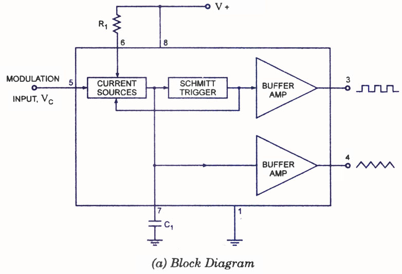
A voltage-controlled oscillator (VCO) is a type of oscillator in which the frequency of output oscillations can be adjusted by varying the amplitude of an input voltage signal. VCOs are commonly utilized in frequency modulation (FM), pulse modulation (PM),...
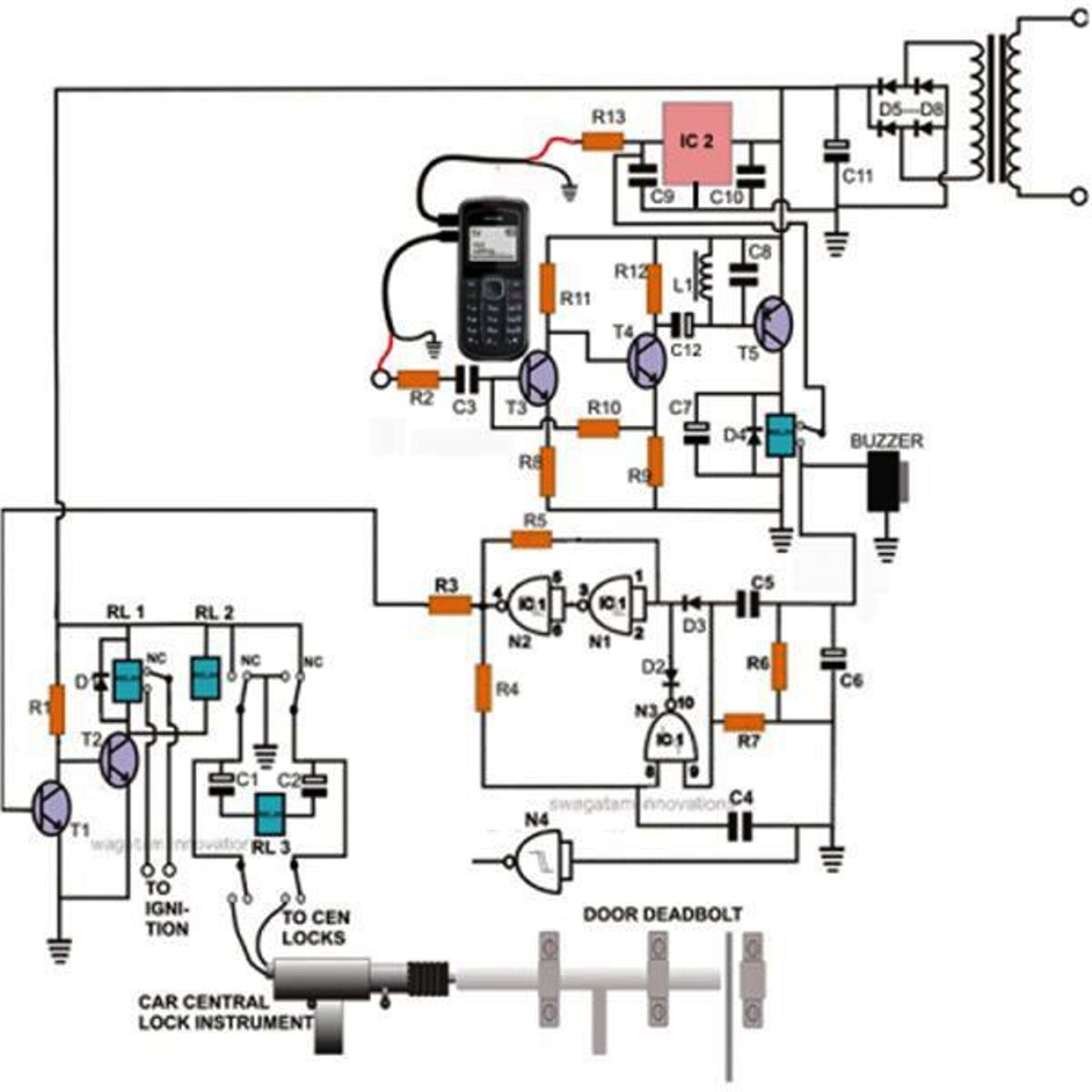
Controlling a door lock through a personal cell phone has become remarkably straightforward. This project outlines the construction of a simple electronic circuit that transforms a conventional door lock into a high-security lock, which can now be operated via...
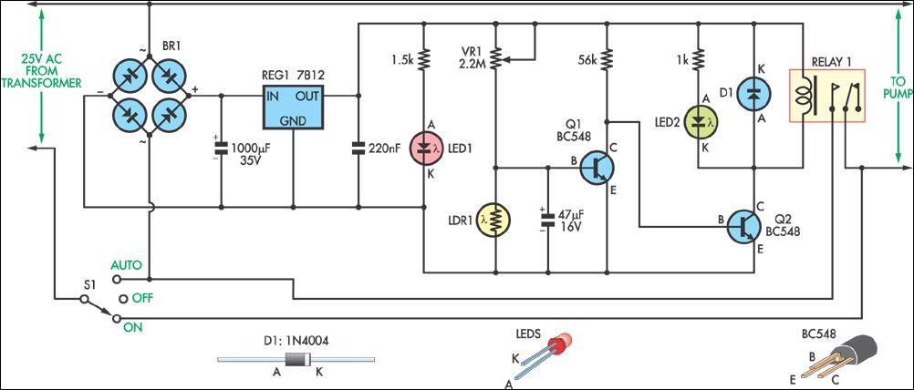
This circuit was designed to control a pump in a garden pond, enabling it to automatically activate at dawn and deactivate at dusk. The circuit utilizes a light-dependent resistor (LDR) to detect ambient light levels, which serves as the primary...

This circuit will disconnect the line supply to audio or video equipment if there has been no input signal for approximately 2 seconds. Switch SI provides manual operation, while switch S2 functions as a reset mechanism. This circuit allows...
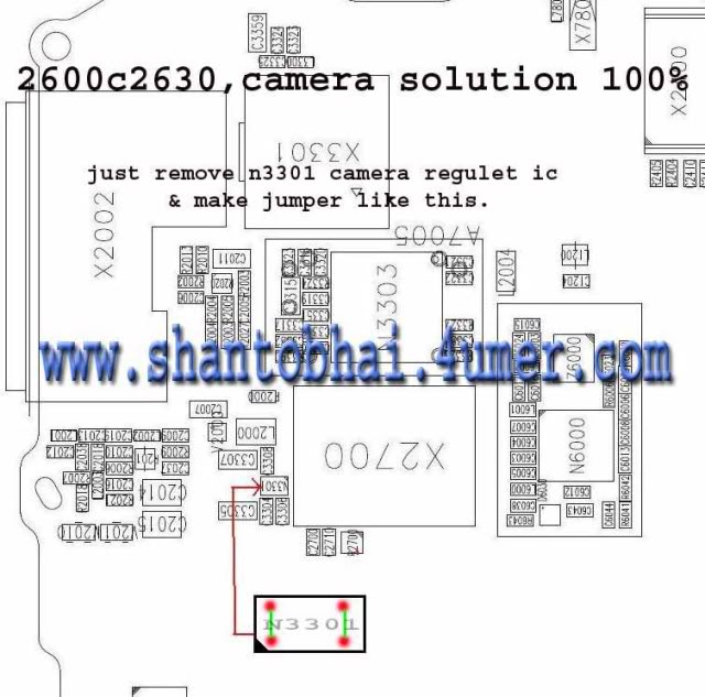
The camera operation failure on the Nokia 2630 has a similar solution to that of the Nokia 2600c, as both devices share the same circuit board. This issue is typically caused by hardware damage or a broken line on...