
220V LED Flasher
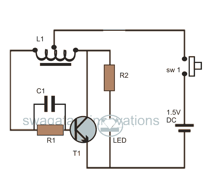
The 220V LED flasher circuit operates by utilizing a simple arrangement of components to create a flashing effect suitable for decorative lighting applications, such as Christmas tree lamps. The primary components include a resistor (R1), which is essential for controlling the current flow through the LED, ensuring it operates within safe limits. The circuit may also include additional components such as a capacitor for timing, a diode for rectification, and a transistor to switch the LED on and off.
In a typical configuration, the resistor R1 is connected in series with the LED, which is powered by a 220V AC supply. The capacitor, when included, is connected in parallel with the LED, forming an RC timing circuit that determines the flashing rate. The diode is used to convert the AC voltage to DC, allowing the LED to flash appropriately. The transistor acts as a switch, controlled by the charging and discharging of the capacitor, enabling the LED to turn on and off at a specified frequency.
This circuit can be assembled on a breadboard or a printed circuit board (PCB) for more permanent installations. The simplicity of the design, combined with readily available components, makes this LED flasher circuit an ideal choice for festive lighting applications, providing an energy-efficient and visually appealing solution. Proper safety precautions should be taken when working with high-voltage circuits, including the use of insulated tools and components rated for the operating voltage.This is a 220V LED flasher circuit which is intended as a reliable replacement to thermally-activated switches used for Christmas tree lamp-flashing. This a cheap circuit and easy to build. Schematic diagram: Component Parts: R1_________ 10.. 🔗 External reference
Related Circuits

The entire series of TTL monostable multivibrators lacks sufficient speed, prompting the need for an ECL voltage swing that accommodates a wide range of small power requirements. This necessitates the use of F series circuits, which offer fast transition...

This series of light switches operates differently from traditional voltage-based systems. These light switches can function directly on the AC power network. The primary components utilized in this circuit are a TRIAC and a Light Dependent Resistor (LDR). The...
The RF engineer occasionally needs to find an instrument that can reliably and quickly test a low-frequency quartz crystal unit. This equipment is often challenging to locate, leading engineers to consult electronic circuits handbooks for schematics that can perform...
This post discusses blue and white LED drivers utilizing a joule thief circuit. Further exploration of the circuit's functionality is provided, along with simulation points. The joule thief circuit is a simple and efficient boost converter that allows for the...

An astable multivibrator, commonly referred to as a free-running multivibrator, is a circuit that generates rectangular waves without the need for external triggering. The timing characteristics of this circuit are determined by the values of the resistors and capacitors...
A simple count-down LED timer that counts in minutes and seconds. Three buttons below the LED provide control of the unit, allowing you set the desired countdown time in minutes and seconds and a start/stop button. Completion of the...