
LED audio peak level
The peak level indicator circuit employs a CMOS inverting Schmitt trigger (74C14) to effectively monitor signal levels and provide visual feedback through an LED. The circuit is designed to respond accurately to transient signals, making it suitable for audio applications such as tape recorders and mixing consoles.
The input stage of the circuit features a half-wave rectifier (D1) that converts the incoming AC signal into a unidirectional voltage. This rectified voltage is then fed into a resistor (R1), which acts as a voltage divider, setting the threshold at which the Schmitt trigger activates. The Schmitt trigger has a defined upper threshold, which is influenced by the supply voltage; for a 5V supply, this threshold is set at 3.6V. When the voltage across R1 exceeds this threshold, the output of the second Schmitt trigger transitions to a high logic level (logic [H]).
Feedback is provided to the input of the second Schmitt trigger through a capacitor (C2). This feedback mechanism allows the circuit to maintain the high output state for a brief period after the input signal has dropped, effectively capturing short-duration peaks. The duration for which the output remains high is determined by the RC time constant formed by R1 and C2.
When the output of the second Schmitt trigger is high, the output of the third Schmitt trigger will be low (logic L), which in turn activates the LED (D4). This LED serves as a visual indicator that the input signal has exceeded the defined threshold, alerting the user to potential clipping or distortion in the audio signal.
Adjustment of the trimmer resistor (TR1) allows for fine-tuning of the maximum input level that the peak indicator will respond to, providing flexibility in various applications. The overall design ensures that the peak level indicator is not only sensitive to short signals but also maintains a high input impedance, minimizing loading effects on the source signal.
The component selection includes a 1MΩ resistor (R1), a 150nF capacitor (C2), a 100nF capacitor (C1), a series of 1N4148 diodes (D1-2-3), a red LED (D4), and a 1MΩ trimmer (TR1), all of which contribute to the circuit's performance and reliability.A peak level indicator when a signal exceeds a certain maximum value. It can be quite useful, for instance, with tape recorders, mixing consoles etc. One of the most important requirements of a peak level indicator is that it should respond to very short signals. The circuit is built using a CMOS inverting Schmitt trigger type 74C14. The input impedance of the peak indicator is fairly high. The value depends to some extent on the position of TR1. The unit functions as follows. The input is half- wave rectified by D1. When the voltage across R1 exceeds the upper trigger threshold, a logic [H] is produced at the output of the second Schmitt trigger.
The trigger threshold depends on the supply voltage. With a 5V supply the trigger level is 3.6V. The positive pulse at the output of the second trigger is feedback to the input via C2. If the input signal was very short, the logic H level will be maintained during the charging time of C2. This time is determined by the values of C2 and R1. During this time the output of the third trigger is logic L, so that LED D4 lights up as an indication that the level of the input signal is too high.
The TR1 trimmer is adjusted to the maximum desired level that the peak indicator should begin to function at. Part List R1=1Mohms C2=150nF 100V MKT IC1=74C14 TR1=1Mohms trimmer D1-2-3=1N4148 C1=100nF 100V MKT D4=RED LED DIODE
🔗 External reference
Related Circuits
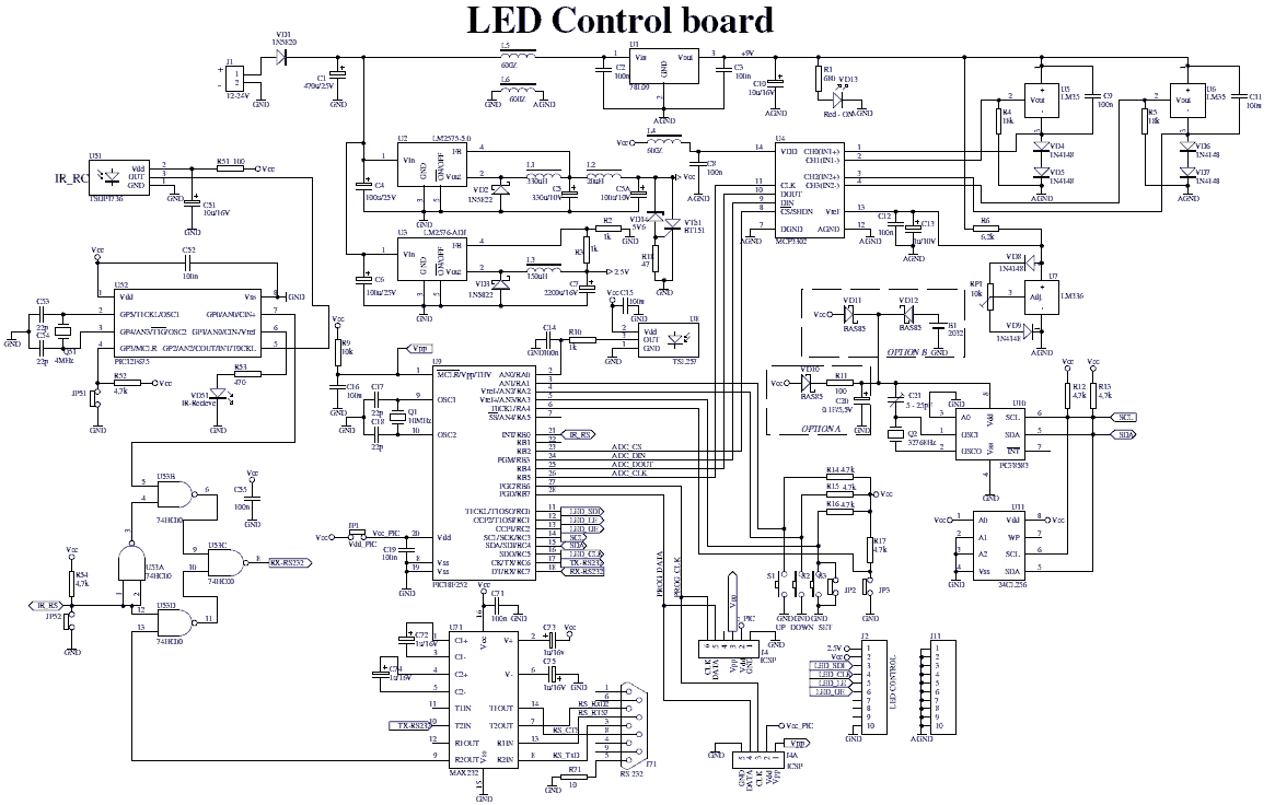
The device comprises two parts: LED control board and LED display board. The two PCBs are designed to fit together one behind the other using two sets of dual row connectors and 4 spacers. One of these connectors is...
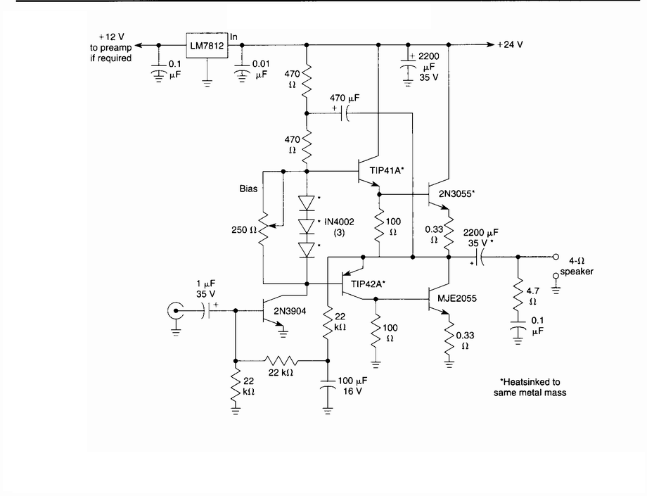
This circuit is a general-purpose 10-W audio amplifier designed for moderate-power public address (PA) systems or as a modulator in an AM transmitter. By applying higher voltages and adjusting the bias resistors, it is possible to achieve output power...
In certain industries, a computer-controlled 4-20 mA current loop is utilized to manage various equipment. This current loop is employed to transmit a signal over a distance. The 4-20 mA current loop is a standard method for transmitting analog signals...
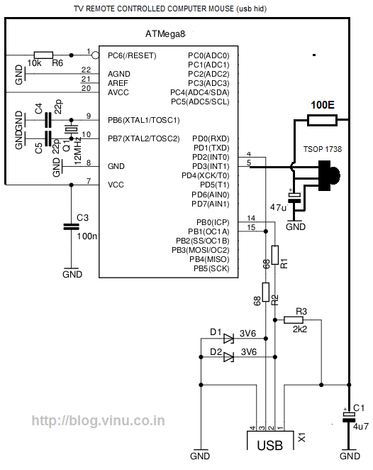
While lying in bed and watching movies on a laptop, the idea arose that having a remote control would simplify the tasks of pausing, playing, fast forwarding, rewinding, adjusting volume, and playing the next track without needing to approach...
A small comparator (MAX9060/MAX9061 or MAX9028) safeguards the LED driver in a backlit display when the LEDs are disconnected, by producing a shutdown signal that eliminates the LED voltage. The MAX9060/MAX9061 and MAX9028 are high-speed voltage comparators designed for applications...
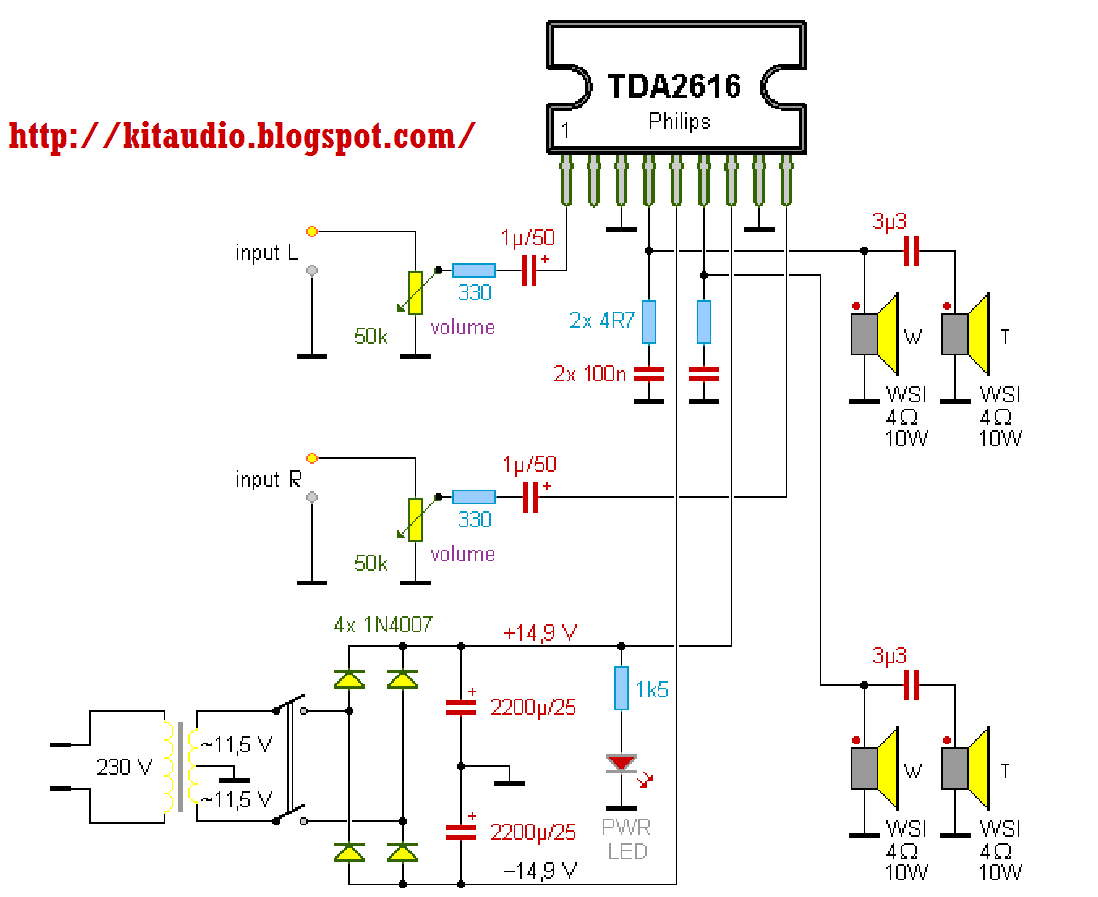
The TDA2616 is a hi-fi stereo amplifier designed for mains fed applications, such as stereo radio and TV. The circuit is optimally designed for symmetrical power supplies, but is also well-suited to asymmetrical power supply systems. An output power...
Warning: include(partials/cookie-banner.php): Failed to open stream: Permission denied in /var/www/html/nextgr/view-circuit.php on line 713
Warning: include(): Failed opening 'partials/cookie-banner.php' for inclusion (include_path='.:/usr/share/php') in /var/www/html/nextgr/view-circuit.php on line 713