
Protect LED Driver in Backlit Displays
The MAX9060/MAX9061 and MAX9028 are high-speed voltage comparators designed for applications such as LED driver protection in backlit displays. These comparators operate with low supply voltages and are capable of providing rapid response times, which are essential for minimizing power consumption and enhancing the reliability of the LED driver circuit.
In a typical application, when the LEDs are disconnected from the circuit, the voltage across the LED driver may increase to potentially damaging levels. The comparator continuously monitors the voltage at the output of the LED driver. Upon detecting a voltage that exceeds a predefined threshold, the comparator generates a shutdown signal. This signal is then used to deactivate the LED driver, effectively removing the LED voltage and protecting the driver from damage due to overvoltage conditions.
The MAX9060/MAX9061 features a single comparator, while the MAX9028 is available in a dual comparator configuration, allowing flexibility depending on the design requirements. These devices can operate from a supply voltage as low as 2.7V, making them suitable for battery-operated applications. Additionally, they offer a fast response time, typically in the nanosecond range, which is crucial for applications where rapid changes in voltage levels occur.
The integration of these comparators into the LED driver circuit enhances the overall robustness of the backlit display system, ensuring that the components remain within safe operating limits during unexpected conditions such as LED disconnection. Proper selection and implementation of the MAX9060/MAX9061 or MAX9028 can significantly improve the durability and performance of LED driver circuits in various electronic devices.A tiny comparator (MAX9060/MAX9061 or MAX9028) protects the LED driver in a backlit display when you disconnect the LEDs, by generating a shutdown signal that removes the LED voltage.. 🔗 External reference
Related Circuits
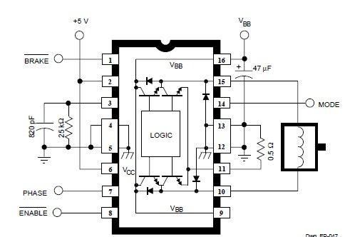
The circuit operates by using a clock signal to drive four D-flip-flops in the control section, which store the on/off state of each current direction for the two stepper motor coils. The flip-flops create a finite state machine (FSM)...
This is a tutorial for beginners who have recently started learning about electronics. The author has prior experience in programming with C and Python. The schematic presented in this tutorial is designed for novice electronics enthusiasts who are transitioning from...
This is a basic Buzzer driver circuit with resonance frequency approximately 5 kHz, 85 dBA. It operates on 3 to 28 V DC at 6 mA. The basic buzzer driver circuit is designed to generate an audible tone by driving...
This simple DC servo motor circuit design can be utilized in various electronic projects. The circuit schematic illustrates that this DC servo motor driver employs a single integrated circuit along with a few external electronic components. For bidirectional DC...
Conventionally, a MOSFET with a voltage rating of 1500V or a Half-Bridge configuration utilizing two MOSFETs rated at 800-900V is employed for Switch Mode Power Supply (SMPS) applications that require input voltages exceeding 380Vac. However, these methods present challenges,...
The LM3915 is a monolithic integrated circuit that senses analog voltage levels and drives ten LEDs providing a logarithmic 3 dB/step analog display. LED current drive is regulated and programmable, eliminating the need for current limiting resistors. More: This...