
Solar Garden LED Lighting
An oscillator needs feedback called positive feedback. Positive feedback creates noise or oscillation in a correctly designed circuit. An oscillator must be self-starting, and the circuit in this project starts to oscillate by detecting a voltage on the base. The transistor amplifies this, and a larger waveform (larger voltage change) appears on the collector. This is then passed to the base so that oscillation continues. For oscillation to occur, the feedback signal must be delayed by a small amount of time. This small amount of time determines the frequency, and the feedback signal has another characteristic. It is presented to the base with an opposite polarity to that on the collector. To be more precise, the voltage must be moving in the opposite direction. This is called "180° out of phase." This is achieved by the inductor and the 1n2 capacitor. It is known that a capacitor creates time to charge, but an inductor also has a delay factor. When the transistor turns off, the magnetic flux collapses and produces a high voltage. This voltage is high enough to illuminate the LED, and the graph shows that when the LED is removed from the circuit, the voltage produced by the inductor has a peak of about 3.5V. The area under the peak represents energy, and this is absorbed by the LED to produce light. The LED also reduces the peak to 2.3V, as this is the maximum voltage of a white, super-bright LED.
The solar garden light can be examined by purchasing one from a low-cost store. If an oscilloscope is available, the waveform on the 1n2 capacitor and across the LED can be observed. The waveform across the capacitor is an incredible 10V peak-to-peak, with part of the waveform going negative by 4V. During the negative excursion, the transistor is turned off, and the magnetic flux produced by the current flow in the top inductor collapses very quickly, producing a high voltage that has an opposite polarity to the energizing voltage. This voltage is passed to the LED, resulting in light production. The short pulses of energy delivered to the LED occupy about 20% of the total time, but the energy they deliver produces a light output equal to a constant DC voltage. By delivering short pulses, only about 30% of the energy is needed to produce the same illumination as a constant voltage. A resistor does not have a delay factor, as a voltage at one end will appear immediately at the other end, allowing for the explanation of the delay time for an inductor by connecting an inductor in series with a resistor.The circuit consists of two stages. The first stage is a "switch" or cut-off device. It detects a voltage above 0.7v from the solar panel and the resistance between its collector-emitter terminals reduces to a very small value. The 10k resistor allows the voltage on the solar panel to rise above 0.7v during bright sunlight, while the 100k discharges the 100p when the voltage is very low and the capacitor holds a charge to keep the transistor turned on when the voltage is "high".
When the resistance between the collector-emitter terminals of the first transistor is low, it is turned ON, and the second transistor does not get enough voltage on its base for it to operate as an oscillator. The SOLAR CELL actually consists of a number of cells as each cell only generates about 0.5v to 0.6v. The Solar Cell in our model consists of 4 cells and produces approx 2v with bright sunlight. The short-circuit current produced is about 30mA and although this is not the correct way to determine the current capability of the cell, it has been given to help you select a suitable cell (or set of cells).
The current will drop considerably when the solar cell is connected to a 1.2v battery via a diode and our project delivered 8mA. The purpose of the first transistor is to keep the second stage OFF when the solar cell detects sunlight.
This allows the energy from the solar cell to be passed to the rechargeable battery. The second transistor is an oscillator. To see how it works we remove the first transistor. The second transistor works by itself. The components in the circuit are: the transistor, the two chokes, the 6k8 resistor, the 1n2 capacitor and the LED. An oscillator needs feedback called POSITIVE FEEDBACK. Positive feedback creates noise or "oscillation" in a correctly designed circuit. An oscillator must be self-starting and the circuit in this project starts to oscillate by detecting a voltage on the base.
The transistor amplifies this and a larger waveform (larger voltage- change) appears on the collector. This is then passed to the base so that oscillation continues. For oscillation to occur, the feedback signal must be delayed by a small amount of time. This small amount of time determines the frequency and the feedback signal has another feature (or characteristic).
It is presented to the base with an opposite polarity to that on the collector. To be more precise, the voltage must be moving in the opposite direction. This is called "180° out of phase." This is achieved by the inductor and the 1n2 capacitor. We all know a capacitor creates time to charge, but an inductor also has a delay-factor. When the transistor turns off, the magnetic flux in collapses and it produces a high voltage. This voltage is high enough to illuminate the LED and the graph shows that when the LED is removed from the circuit, the voltage produced by the inductor has a peak of about 3.5v. The area under the peak represents energy and this is absorbed by the LED to produce light. The LED also reduces the peak to 2.3v as this is the maximum voltage (or characteristic voltage) of a white, super-bright LED.
Make an effort to buy a Solar Garden Light from a $2 shop and pull it apart, just to see how it works. If you have a CRO, you will be able to view the waveform on the 1n2 capacitor and across the LED. The waveform across the capacitor is an incredible 10v p-p with part of the waveform going negative by 4v.
During the negative excursion, the transistor is turned off and the magnetic flux produced by the current-flow in the top inductor collapses very quickly and produces a high voltage that has an opposite polarity to the energising voltage. This voltage is passed to the LED and light is produced. The short pulses of energy delivered to the LED occupy about 20% of the total time but the energy they deliver produces a light-output equal to a constant DC voltage.
By delivering short pulses, only about 30% of the energy is needed to produce the same illumination as a constant voltage. A resistor does not have a delay-factor, as a voltage at one end of it will appear immediately at the other end, so we can explain the delay-time for an inductor by connecting an inductor in series with a resistor.
There have been many technical descriptions on how an inductor delays a signal, but never a simplified description. 🔗 External reference
Related Circuits
In various electronics-level adjustments, such as LED drivers for LCD panel backlight controls, the AD5228 can be utilized. A manually adjustable LED driver is illustrated. The AD5228 is a dual-channel, digitally controlled potentiometer (DCP) that can be employed in applications...
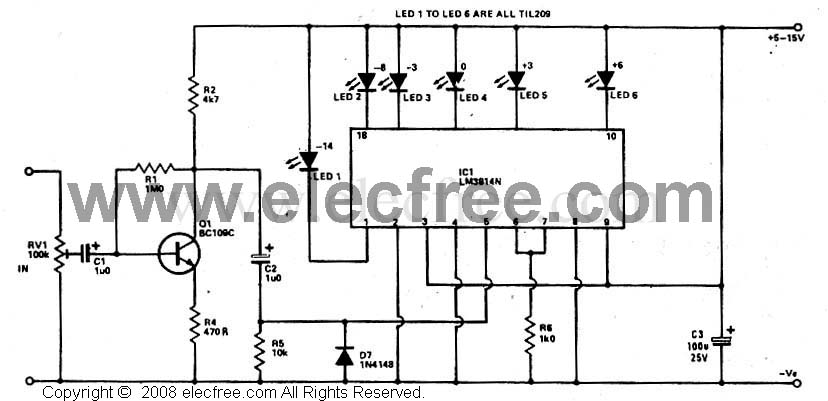
This is an LED VU Meter circuit using the LM3914 IC, designed to visually represent audio signals in stereo or sound applications. The circuit is straightforward to assemble, utilizing a single integrated circuit (IC) to display 10 levels of...
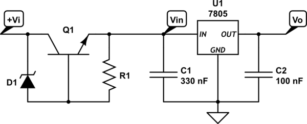
A power supply circuit is designed to convert 24VAC to 5VDC. An L7805CV voltage regulator is used; however, after rectification with a bridge rectifier and smoothing with a 33µF electrolytic capacitor, the input voltage remains at 40V peak, which...
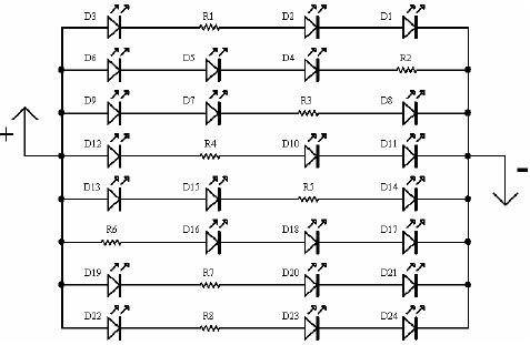
A light-emitting diode (LED) lamp is a solid-state lighting device that utilizes light-emitting diodes as its light source. LEDs are a cost-effective and convenient choice for various lighting applications. They are available in an extensive range of colors, styles,...
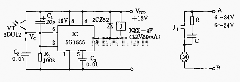
The control circuit consists of an NE555 timer and a phototransistor, along with resistors R1, capacitors C1 and C2, among other components. The photodiodes 3DU12 respond to sunlight by decreasing their resistance, which causes the voltage at the 555...
The following circuit illustrates a Dancing LEDs electronic circuit diagram. This circuit is based on the LM358 integrated circuit. Features: IC1A amplifies the signal. The Dancing LEDs circuit utilizes the LM358 operational amplifier to create a visually appealing light display....