
Led bar-graph driver

The circuit design employs two CA3290 BiMOS dual voltage comparators, configured to compare an input signal against a reference voltage derived from a voltage divider. The non-inverting inputs of the comparators, labeled A1 and A2, are connected to the output of the voltage divider, which establishes a stable reference voltage. The inverting inputs receive the variable input signal that is to be monitored.
When the input voltage exceeds the reference voltage provided by the divider, the output of the comparators transitions from a low state to a high state. This change in output is used to control the state of the connected LEDs. Specifically, the LEDs will illuminate when the input voltage reaches or surpasses the reference voltage level set by the voltage divider, providing a visual indication of the input signal's status.
The voltage divider can be designed using two resistors, R1 and R2, connected in series across a supply voltage. The junction between R1 and R2 provides the reference voltage to the non-inverting inputs of the comparators. The choice of resistor values will determine the threshold voltage at which the LEDs will turn on, allowing for customization of the circuit's response to varying input signals.
In summary, this circuit effectively utilizes the CA3290 comparators to create a simple voltage monitoring system that activates LEDs based on the comparison of an input voltage with a predefined reference voltage. The design is straightforward and can be adapted for various applications requiring voltage level indication.The circuit uses CA3290 BiMOS dual voltage comparators. Non-inverting inputs of A1 and A2 are tied to voltage divider reference. The input signal is applied to the inverting inputs. LEDs are turned "on" when input voltage the reaches the voltage on the reference divider.
Related Circuits
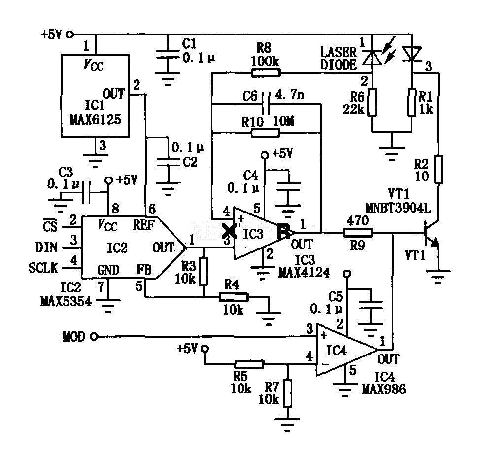
The laser tube drive circuit typically incorporates a photodiode that generates a laser beam proportional to the intensity (optical power) of the current. However, this type of photocell is generally slow and unable to track modulation effectively, particularly for...

These novel relay driver circuits can activate a relay with a coil voltage rating that is double the Vcc. After activation, the relay armature is held in place. The relay driver circuits described are designed for applications requiring the control...
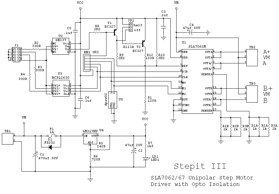
The SLA7062/67 chip is a unipolar driver capable of delivering up to 3 amps. This chip is somewhat difficult to locate and is priced at approximately $10 each. Availability was confirmed through a Google search, which yielded three units...
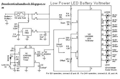
This is a low power voltmeter circuit designed for use with alternative energy systems that operate on 12V and 24V batteries. The voltmeter features an expanded scale that indicates small voltage steps within the 10 to 16 volt range...
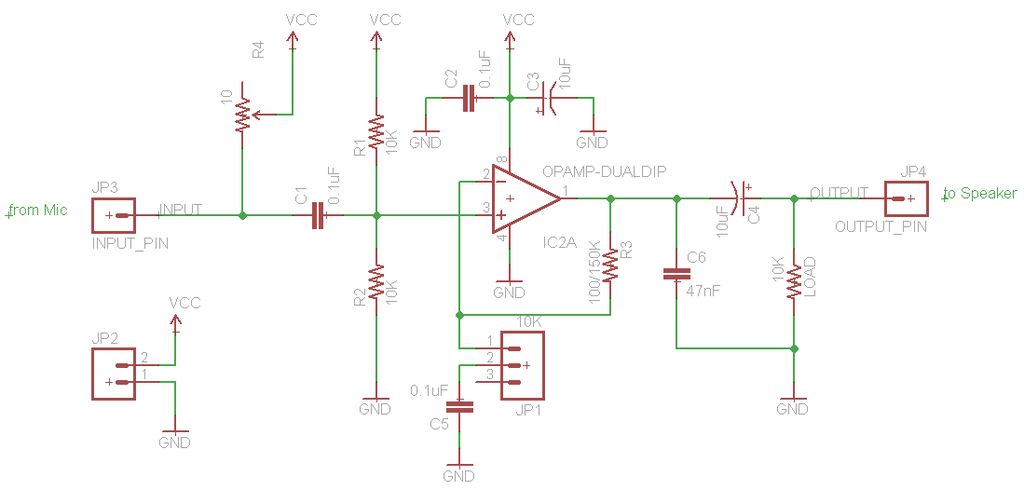
The TL072 operational amplifier is used to amplify an audio signal that is directed to both speakers and an Arduino's analog input. The amplifier is powered by a 12V, 2A wall wart, which is also regulated down to 5V...
A simple forward-reverse motor control driver electronic circuit can be designed using the LB1948M, a two-channel low saturation voltage forward-reverse motor control driver IC. The LB1948M motor driver is suitable for use in 12V system products and can drive...