
555 Voltage Doubler Relay Driver

The relay driver circuits described are designed for applications requiring the control of relays with higher coil voltage ratings than the supply voltage (Vcc) available in the circuit. These circuits employ innovative techniques to ensure reliable operation despite the increased voltage requirements.
The primary components of the relay driver circuit typically include a transistor or MOSFET that acts as a switch, a diode for flyback protection, and the relay itself. The circuit is powered by a voltage supply (Vcc), which is lower than the relay coil voltage rating. The transistor is used to amplify the control signal, allowing it to manage the higher voltage required to energize the relay coil.
When a control signal is applied to the base (for bipolar transistors) or gate (for MOSFETs) of the transistor, it turns on, creating a path for current to flow through the relay coil. This current generates a magnetic field strong enough to pull in the relay armature, connecting the normally open contacts and allowing current to flow through the load connected to the relay.
To safeguard the circuit from voltage spikes generated when the relay is deactivated, a flyback diode is placed in parallel with the relay coil. This diode provides a path for the inductive kickback current, protecting the transistor from potential damage due to high voltage transients.
These relay driver circuits are particularly useful in applications where control signals are limited to low voltages, yet there is a need to control devices that operate on higher voltages. This capability enhances the versatility and reliability of relay-based control systems in various electronic applications.These novel relay driver circuits have the ability to pick up a relay with a coil voltage rating equal to double Vcc. After pickup, the relay armature is h.. 🔗 External reference
Related Circuits

This project involves controlling a small DC motor, sourced from an old personal cassette player, using the ATmega8 microcontroller. The ATmega8 features three PWM channels, of which two are utilized in this application. The PWM signals are sent to...
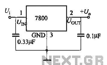
A fixed three-terminal integrated voltage regulator can be directly employed in various electronic devices as a voltage regulator. It features internal protections such as overcurrent protection, thermal protection, and safe operating area protection, making the circuit easy to use,...
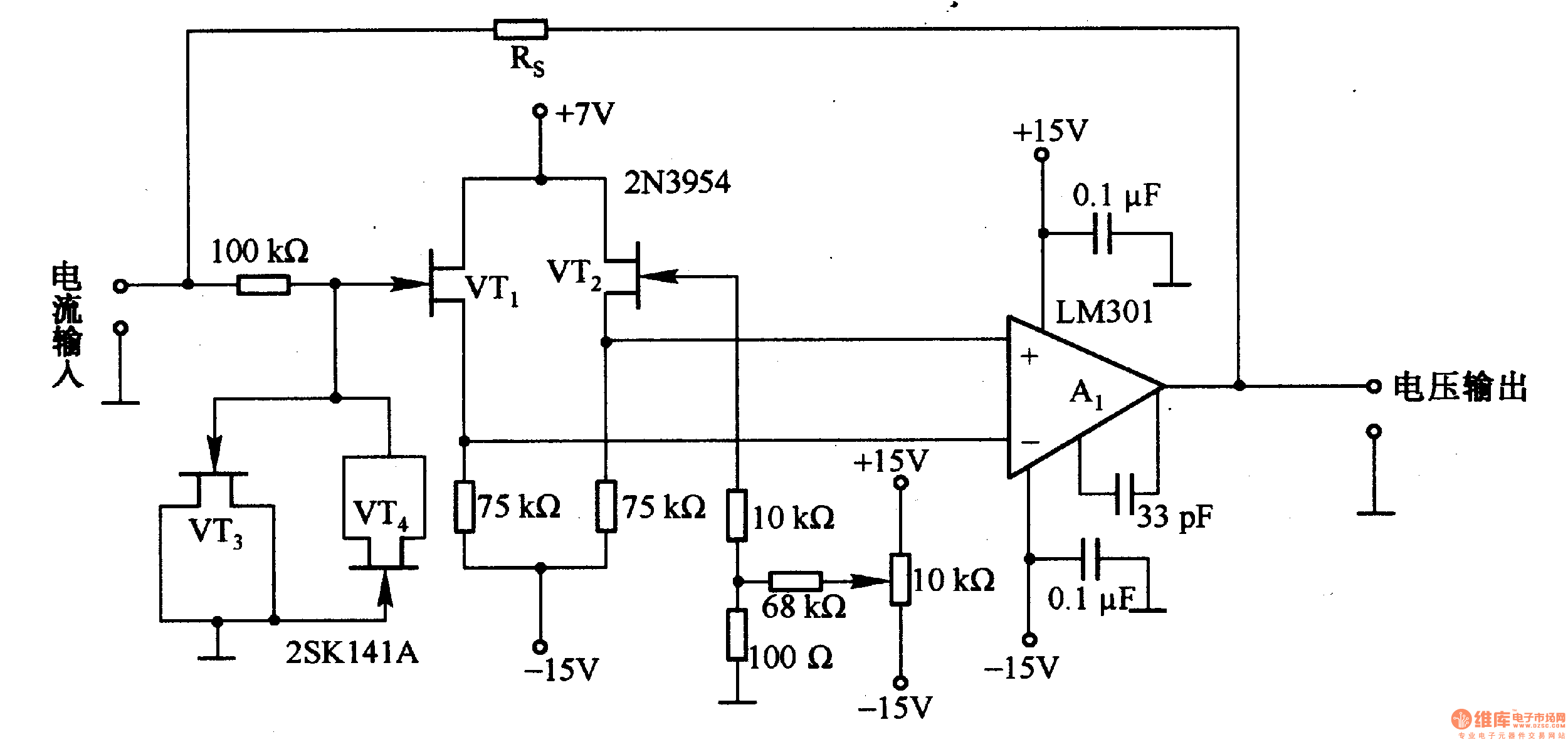
This is a low-input impedance conversion circuit with the reference resistor RS connected to the amplifier's feedback loop, resulting in an input impedance close to zero. The input current flows into the output end of the operational amplifier (Op-Amp)...
This circuit addresses the challenge of transmitting data over a cable that lacks available conductors. The data is modulated using On-Off Keying (OOK) and superimposed on a high-frequency carrier, allowing it to be transmitted over a low-voltage power supply...
The NJM2670 is a general-purpose 60V dual H-bridge drive integrated circuit (IC). It features a pair of H-bridges, a thermal shutdown circuit, and an alarm output. The alarm output is capable of detecting application issues, thereby significantly enhancing system...
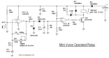
This circuit diagram illustrates a voice-operated relay, which functions similarly to a sound-activated switch circuit. It activates and deactivates the switch based on sound input. The output switch of this circuit is controlled by a relay. The release time...
Warning: include(partials/cookie-banner.php): Failed to open stream: Permission denied in /var/www/html/nextgr/view-circuit.php on line 713
Warning: include(): Failed opening 'partials/cookie-banner.php' for inclusion (include_path='.:/usr/share/php') in /var/www/html/nextgr/view-circuit.php on line 713