
NC visible laser modulation driver circuit
The laser tube drive circuit is designed to ensure stable operation of the laser system by continuously monitoring and adjusting the optical power output. The use of a photodiode allows for the detection of the laser beam intensity, providing feedback for the control system. However, due to the slow response time of the photodiode, it is not suitable for applications requiring rapid modulation of the laser output.
To address this limitation, the design incorporates a digital-to-analog converter (DAC) that translates digital signals into analog control voltages, thereby enabling precise adjustments to the laser power. The 3-wire serial interface facilitates communication between the DAC and the controlling microcontroller or digital signal processor, allowing for seamless integration into automated systems.
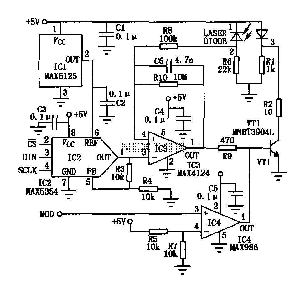
The visible laser modulation driver circuit is equipped with a separate digital input line (MOD) that can be used to trigger modulation events. The comparator (IC4) serves to compare the feedback signal from the photodiode with a reference voltage, ensuring that the output remains within specified limits. The open-drain output configuration allows for flexibility in interfacing with various components, including the transistor (VT1) that acts as a switch to pulse the laser diode (VD1) based on the digital commands received.
This architecture not only enhances the performance of the laser tube drive circuit but also allows for effective digital communication, making it suitable for applications in laser marking, engraving, and other industrial processes where precise control of laser output is crucial. The overall design emphasizes stability, responsiveness, and adaptability to varying operational demands.In the laser tube drive circuit are often provided with a photodiode, which generates a laser beam is proportional to the intensity (optical power) of the current, but in response to this type of photocell mostly relatively slow, generally can not track modulation peak light laser tube power. Therefore, this drive circuit is achieved by monitoring the average optical power to control the laser generator. NC visible laser modulation driver circuit is shown, which includes a digital to analog converter 10 3-wire serial interface (DAC), a visible light laser tube is used to control the output of a constant average optical power; a separate digital input line (MOD), an open-drain output by a comparator (IC4) and VTl, is fed to the laser diode VD1 pulse, digital communications.
Related Circuits
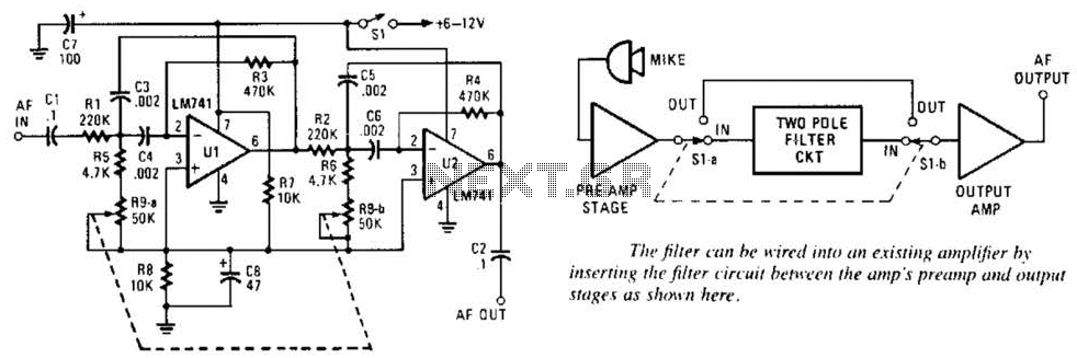
This variable-frequency audio bandpass filter is constructed using two 741 operational amplifiers (op amps) connected in cascade. Both op amps are configured as identical RC active filters, enhancing the selectivity of the overall circuit. The filter has a tuning...
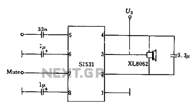
The battery voltage is 1V for a low-frequency amplifying circuit, which can operate with a power supply voltage ranging from 1V to 1.7V, making it suitable for use with small batteries. The circuit provides an output power of 80mW...

This design circuit illustrates an LM1893 power line modem circuit. It is utilized to transfer information between remote locations using the power mains. The circuit employs the LM1893, which functions as a power line interface for half-duplex (bi-directional) communication...

The digital circuit that is particularly useful is the One-Shot circuit, also known as a monostable multivibrator circuit. This circuit exhibits a specific behavior where it generates a single output pulse in response to an input trigger. The One-Shot circuit,...
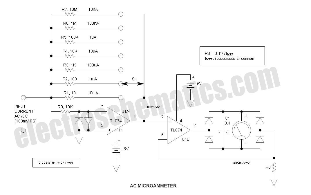
This is a variation of Mr. Marian's "Simple Micro Ampere Meter Circuit" that employs active circuitry and an analog meter to measure sensitive DC currents. The circuit in question is designed to provide precise measurements of very low DC currents,...
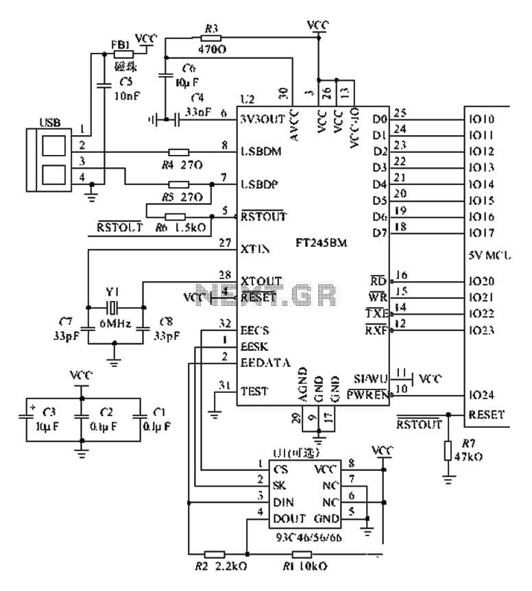
The FT245BM typical hardware circuit operates in bus-powered mode and employs a power-on reset mechanism to initialize the device. The clock circuit can be implemented using a 6 MHz crystal oscillator module or a combination of a 6 MHz...
Warning: include(partials/cookie-banner.php): Failed to open stream: Permission denied in /var/www/html/nextgr/view-circuit.php on line 713
Warning: include(): Failed opening 'partials/cookie-banner.php' for inclusion (include_path='.:/usr/share/php') in /var/www/html/nextgr/view-circuit.php on line 713