
LED Battery indicator
The circuit described functions as a voltage monitoring system for a car battery, utilizing a series of LEDs to provide visual feedback on the battery's voltage levels. The primary components include four distinct LEDs and several Zener diodes, which are crucial for establishing reference voltage levels.
The circuit operates by monitoring the voltage across the car battery and lighting up the corresponding LEDs based on predefined voltage thresholds. The green LED (D5) indicates a voltage below 9 V, signaling a bad battery condition. The yellow LED (D7) illuminates at 11 V, indicating a doubtful battery status, while the red LED (D9) lights up at 13 V, suggesting that the battery is functioning properly. The blinking LED (D11) activates when the voltage exceeds 15 V, which serves as a warning that there may be an issue with the alternator or voltage regulator.
The Zener diodes (D6, D8, D10, D12) are integral to the operation of this circuit. Each Zener diode is selected to clamp the voltage at specific levels that correspond to the activation points of the LEDs. For example, the 4.7 V Zener (D6) sets a lower threshold, while the 9.1 V Zener (D10) sets the point at which the battery is considered to be in a bad state. The circuit may require adjustments, such as replacing Zener diodes, if the measured voltage values deviate significantly from the expected thresholds.
Transistors (T1, T2, T3, T4) of type BF 256B are employed in the circuit to amplify the signals from the Zener diodes, ensuring that the LEDs can be driven effectively with sufficient current. The 1N4002 diodes (D1, D2, D3, D4) serve as protection diodes, preventing reverse polarity that could damage the circuit components.
In summary, this battery voltage monitor circuit provides a simple yet effective means of assessing the health of a car battery through visual indicators, utilizing a combination of LEDs, Zener diodes, and transistors for reliable operation. Proper assembly and verification of the activation points are essential for ensuring accurate performance.This battery allows the indicator to the car battery voltage monitor. The indicator has four LEDs which indicate power. The more LEDs, the higher the voltage. The last LED is a flashing LED. It comes on when the accuspaning limit of about 15 V limit. This is a sign that something is wrong with the alternator or voltage regulator. The other LEDs light up in 9 V (D5: bad battery), 11 V (D7: battery doubtful) and 13 V (D9: battery ok). Build the circuit and verify the above activation points. If the measured values ??much different from the above, try other Zener diodes. Of 300 mW Zener are sufficient for the circuit. D1, D2, D3, D4 = 1N4002 D5 = LED green D7 = yellow LED D9 = red LED D11 = LED blinking D6 = 4.7 V/300 mW zener D8 = 6.2 V/300 mW zener D10 = 9.1 V/300 mW zener D12 = 5.1 V/300 mW zener T1, T2, T3, T4 = BF 256B 🔗 External reference
Related Circuits
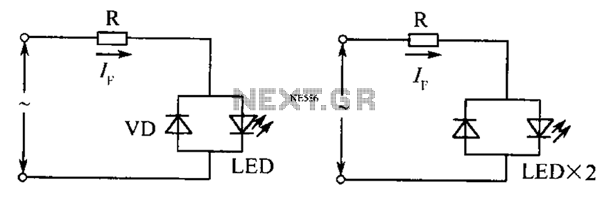
The circuit operates effectively even when the polarity of the voltage or the power supply is reversed. It functions with DC drives similar to AC drives, utilizing a current limiting resistor R. The value of this resistor is determined...
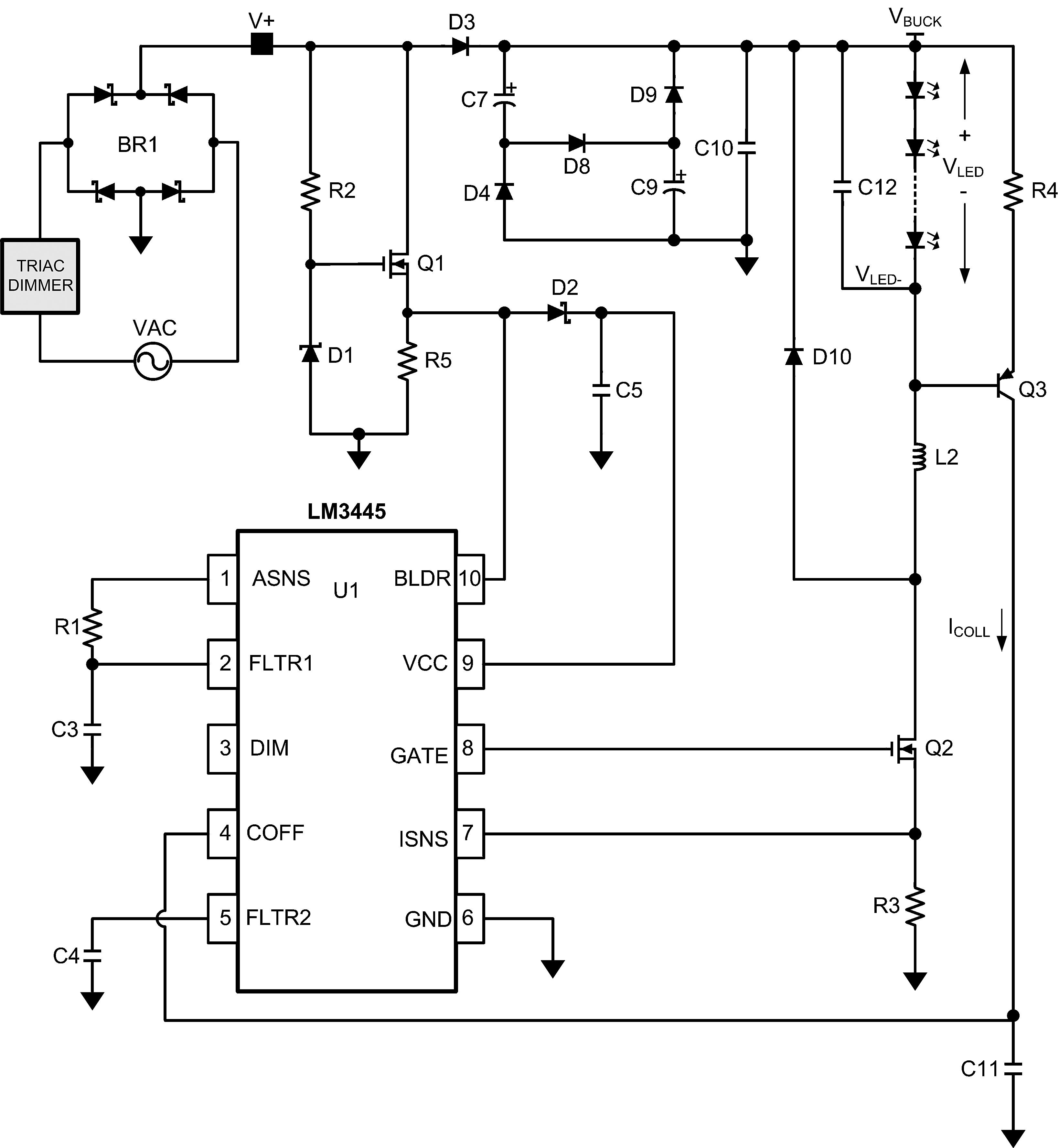
The LM3445 is an adaptive constant off-time AC/DC buck (step-down) constant current controller designed for compatibility with triac dimmers. The LM3445 is a specialized integrated circuit that functions as a constant current controller in AC/DC applications, particularly suited for LED...
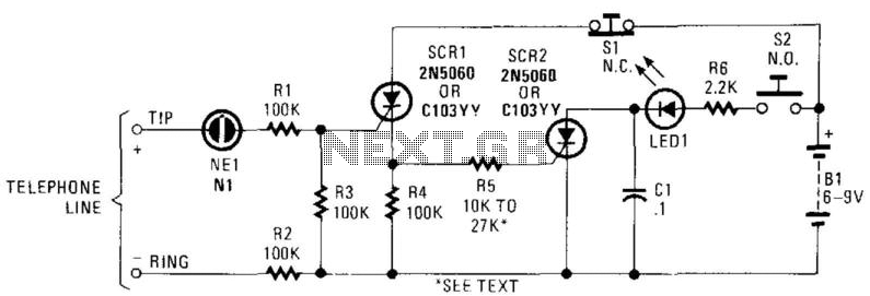
In this circuit, the ringing voltage on a telephone line causes NE-1 to break over, triggering SCR1, which in turn triggers SCR2. If a call has been received, depressing S2 will cause LED1 to light. Depressing S1 resets the...
This article discusses a fully automatic 6V 4.5AH battery charger circuit that utilizes the LM317T integrated circuit along with a few additional components. The circuit is designed to charge a 6V lead-acid battery. The circuit utilizes the LM317T voltage regulator,...

This application note discusses the use of SEPIC power modules to supply the necessary power for driving high-brightness LED arrays. These arrays serve as display backlights and necessitate a wide dimming range. The SEPIC configuration offers an efficient and...
Twelve LEDs can be arranged in a circle to represent the twelve hours of a clock face, while an additional twelve LEDs can be arranged in an outer circle to indicate five-minute intervals within the hour. Four additional LEDs...