
thermostat for 1kw space heater scr controlled
The described circuit employs a heating element that operates under the control of two SCRs configured in a back-to-back arrangement, allowing for effective control of the heating process during both halves of the AC waveform. The use of SCRs is advantageous due to their ability to handle high current loads, making them suitable for applications such as heating elements in industrial or domestic settings.
The pulse transformer plays a critical role in this circuit by providing the necessary isolation and triggering mechanism for the SCRs. The three identical windings serve distinct functions: two windings are responsible for generating the trigger pulses that activate the SCRs, while the third winding is utilized to drive a pair of PNP transistors. These transistors are configured to alternate the supply of pulses to the transformer, ensuring that the SCRs are triggered appropriately at the beginning of each AC half-cycle.
The control strategy implemented in this circuit is particularly noteworthy. By applying trigger pulses to both SCRs at the commencement of each AC half-cycle, the circuit ensures that only one SCR will conduct based on the AC polarity. This selective conduction is essential for maintaining the correct direction of current flow through the heating element, thereby optimizing the heating efficiency and protecting the components from potential damage due to reverse polarity.
In summary, this circuit design effectively utilizes SCRs and a pulse transformer to control a heating element, demonstrating a reliable method for managing AC power in heating applications. The alternating pulse supply from the PNP transistors guarantees that the SCRs are activated in a synchronized manner with the AC signal, providing efficient and safe operation of the heating element.The heater element (not shown) is connected in series with two back to back 16 amp SCRs (not shown) which are controlled with a small pulse transformer. The pulse transformer has 3 identical windings, two of which are used to supply trigger pulses to the SCRs, and the third winding is connected to a PNP transistor pair that alternately supply pulses to the transformer at the beginning of each AC half cycle.
The trigger pulses are applied to both SCRs near the beginning of each AC half cycle but only one conducts depending on the AC polarity.. 🔗 External reference
Related Circuits
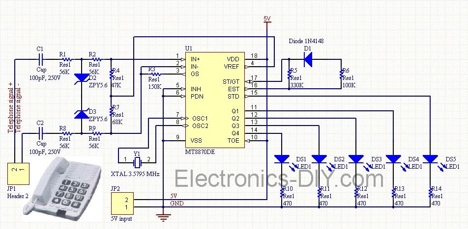
Cellphone Operated Land Rover (Mobile Phone Operated Robot). In this project, the robot is controlled by a mobile phone that makes a call to the mobile phone attached to the robot. The cellphone operated Land Rover project involves the design...
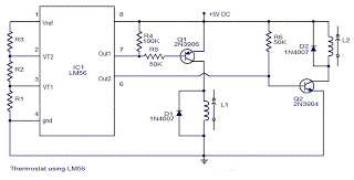
The values of the LM56 thermostat project circuit diagram for resistors R1, R2, and R3 at the travel points VT1 and VT2 can be determined using the following equations. This electronic circuit thermostat with the IC LM56 serves as...
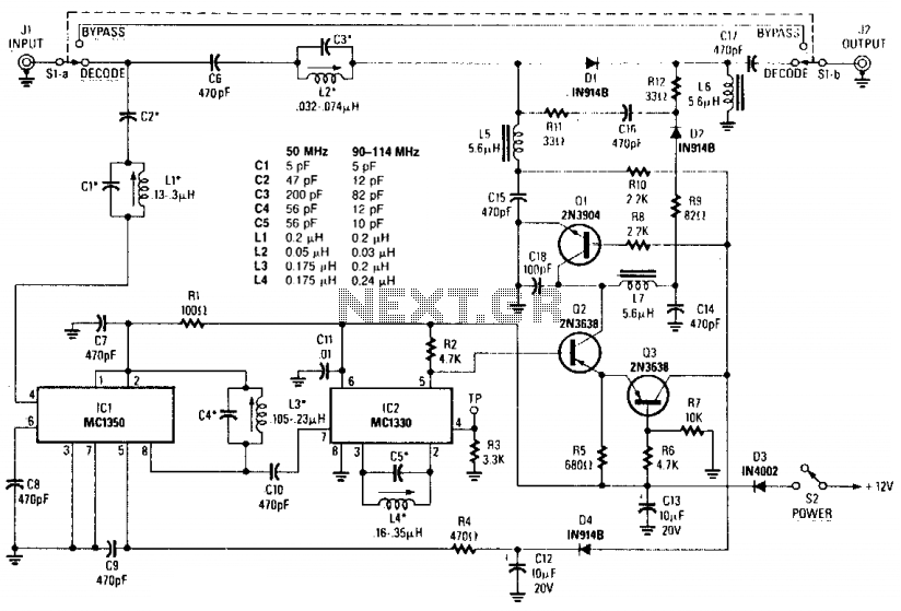
For the outband decoder to function properly, the cable company must deliver a minimum signal strength of 1 millivolt. The component values for capacitors C1-C5 and inductors L1-L4 can be referenced in Table 1. This circuit includes an amplifier...
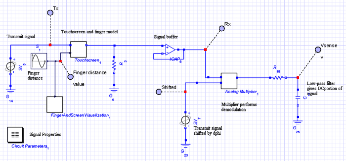
The objective of this project is to develop a model of a capacitive touch screen, which includes the physical modeling of a user's finger, the materials of the touch screen, and the touch-detection circuitry. A capacitive touch screen functions...
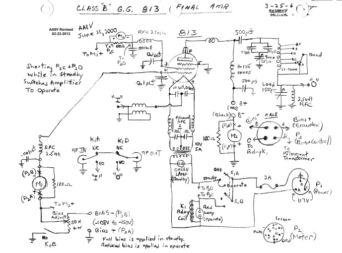
The input impedance of a grounded grid amplifier is typically several hundred ohms. While most vacuum tube transmitters can drive such an impedance without issue, solid-state transmitters, which are designed for loads close to 50 ohms, generally struggle with...
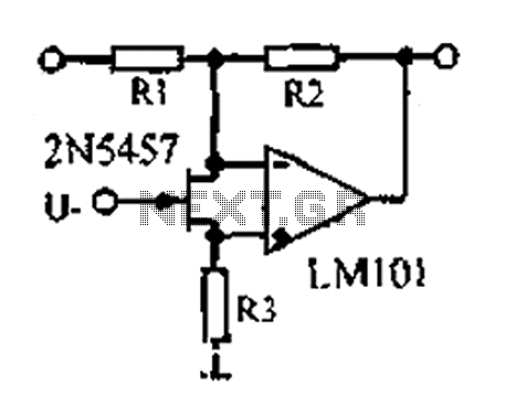
A 1.53 voltage-controlled gain amplifier (VGA) utilizes a FET connected between the two inputs of the operational amplifier (op-amp) as a voltage-controlled resistance. The resistance changes linearly with voltage and varies from several dozen square ohms, exhibiting excellent control...
Warning: include(partials/cookie-banner.php): Failed to open stream: Permission denied in /var/www/html/nextgr/view-circuit.php on line 713
Warning: include(): Failed opening 'partials/cookie-banner.php' for inclusion (include_path='.:/usr/share/php') in /var/www/html/nextgr/view-circuit.php on line 713