
LED Circuit with Timer 555
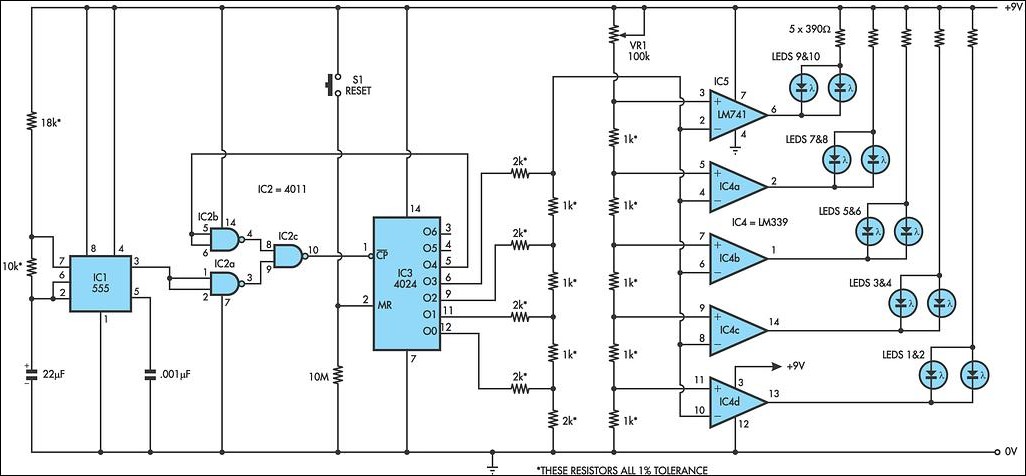
The circuit design integrates a 555 timer configured in astable mode to generate a continuous pulse train, which serves as the clock signal for the binary counter (IC3). The 4024 binary counter counts from 0 to 15 in binary format, with its outputs corresponding to the count state. The NAND gates (IC2a and IC2c) are configured to manage the clock signal and control the operation of IC3. The output O4 from the binary counter is crucial for determining when to disable the clock input to prevent further counting, ensuring that the LED sequence operates correctly without exceeding the defined count.
The digital-to-analog converter (DAC) is constructed using a resistor ladder that translates the binary output of the counter into an analog voltage. This voltage is then used as a reference for the comparators (IC4 and IC5), which are set to specific threshold levels determined by the voltage divider. The sequential activation of the comparators allows for a smooth transition of LED illumination, creating a visually appealing sequence that mimics the LED patterns used in professional racing.
The use of a pushbutton switch (S1) provides a manual reset option, allowing the user to restart the LED sequence at any time. The circuit's design emphasizes reliability and simplicity, making it suitable for various applications beyond racing, including educational demonstrations of digital counting and analog signal conversion. The overall functionality, combined with the ability to adjust reference voltages via the trimpot, enhances the versatility and adaptability of the circuit for different user needs.This circuit LED reproduces the first LED sequence at this time used by FISA on behalf of Formula single racing. It may perhaps be alive used with slot car sets (such for example HO shin up AFX/Life Like/Tyco sets) or else means of communication controlled cars.
IC1, a 555 timer IC, is used as a watch pulse generator. Its output is fed via NAND ga tes IC2a and IC2c to IC3, a 4024 binary counter. IC2b inverts the O4 output of 4024 binary counter IC3. originally, IC3 is reset and all its outputs are low, together with O4, which causes IC2b to present-day a rational climax to the pin 8 input of IC2c which after that passes pulses from the 555 timer circuit to the clock input of the 4024. IC3 then begins together with. Following the count has reached binary 1111, the subsequently pulse sends the O4 output of IC3 high, which disables IC2c and IC3 stops with.
The four used outputs of IC3 are connected to a resistor ladder` which acts to the same degree a clear-cut digital to analog convert-er (DAC). As the count increases so does the voltage produced by the side of the top of the ladder and this is connected to the inverting inputs of four comparators inside IC4 (an LM339) and to IC5, which is a 741 op amp furthermore connected while a comparator.
The categorical inputs of the comparators are connected to the taps of a voltage dividing wall, with the drumming voltages settle on using VR1, a 100kO trimpot. As IC3 counts, the rising stepped voltage from the DAC ladder switches the comparators on clothed in sequence, preliminary with IC4d and working up to IC5.
in the same way as both comparator is curved on, its pair off of LEDs is lit; former LEDs 1 & 2, next LEDs 3 & 4 and so on. as soon as all five pairs of LEDs are lit, the then pulse from IC1 moves the binary count of IC3 to 10000, so the DAC voltage drops back to zilch and all LEDs are extinguished.
by the same spell, with too stops, for the reason that the area of high pressure on O4 causes IC2c to check extra gate pulses. The circuit in that case remains reserve until the counter is reset by urgent pushbutton switch S1. This allows a recent sequence to initiate. 🔗 External reference
Related Circuits
To avoid excess ripple output on a power supply feeding a heavy load, usually a large value capacitor is chosen following the rectifier. In this circuit, C1 is only a 470uF capacitor. The gyrator principle uses the effect that...
If a page name is not selected by pressing the button, the previously selected page name continues to be used. The value is stored in EEPROM and may be changed at any time. When the unit is first powered...

The proposed remote control circuit can be utilized to control any electrical device within a range of 100 meters. This concept involves modifying an existing remote bell unit circuit, making the process straightforward. However, the construction aspect necessitates electronic...
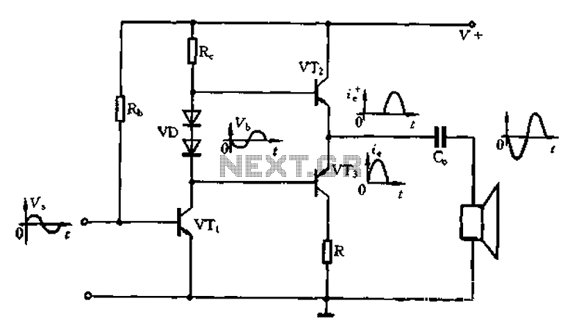
The Class A power amplifier exhibits low distortion; however, it suffers from low efficiency and limited output power, prompting the design of Class B power amplifier circuits. The Class B amplifier operates by shifting the operating point of the...

The circuit diagram for a multiple output digital camera power supply using the MAX1802 is illustrated below. The MAX1802 chip features two buck converters and three boost converters. It accepts an input voltage range of 2.5 to 11V and...

The circuit described below is notable for its low power consumption. With a 9V input and no load at the output, it draws only 50 mA, which is significantly lower than the quiescent current of a 78L05 regulator. The...
Warning: include(partials/cookie-banner.php): Failed to open stream: Permission denied in /var/www/html/nextgr/view-circuit.php on line 713
Warning: include(): Failed opening 'partials/cookie-banner.php' for inclusion (include_path='.:/usr/share/php') in /var/www/html/nextgr/view-circuit.php on line 713