
LED Color Fade Effect circuit diagram
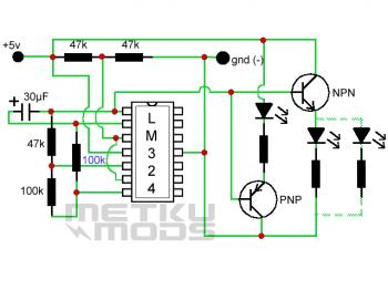
This LED color fade circuit is designed to provide a visually appealing light effect through gradual intensity changes. The fading effect is achieved by utilizing a timing capacitor (30 µF) in conjunction with a resistor (100 kΩ) that determines the charge and discharge rate of the capacitor. By replacing the fixed resistor with a linear potentiometer, the user can customize the fading speed, making the circuit versatile for various applications.
The LM324 operational amplifier serves as the core of the circuit, where two of its four op-amps are configured to create the necessary control signals for the fading effect. The op-amps are set up in a feedback configuration that allows for smooth transitions in voltage levels, which in turn modulates the current flowing through the LED. The BC547 transistor acts as a switch, controlling the LED's on/off state based on the output from the op-amps.
The ultra-bright red LED, paired with a 220 Ω current-limiting resistor, ensures that the LED operates within safe parameters while achieving high brightness. The resistor is critical in preventing excess current that could damage the LED.
This circuit is suitable for decorative lighting, indicators, or any application where a gradual change in light intensity is desired. The design is simple yet effective, making it accessible for hobbyists and professionals alike.This is the circuit of LED color fade effect. Just like the name of the circuit, the light intensity of LEDs in this circuit will fade from high intensity to low intensity and then off. 30 uF condensator and the resistor marked with blue 100k control the speed of the fading. You can replace the 100 kilo ohm resistor with 100k linear potentiometer so you can adjust the speed any time. LM324 is an OP-Ampamplifier. There 4 op amp, and we just use 2 op amp in abovecircuit diagram. You may use the other 2 op-amp to build another similar circuit. Transistor is BC547 and the led isultra brightred with 220 ohm resistor in series. We aim to transmit more information by carrying articles. Please send us an E-mail to wanghuali@hqew. net within 15 days if we are involved in the problems of article content, copyright or other problems. We will delete it soon. 🔗 External reference
Related Circuits
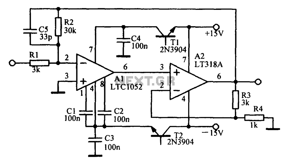
Amplifying circuit diagram to enhance the output current and voltage. An amplifying circuit is designed to increase the amplitude of an input signal, resulting in a higher output current and voltage. This type of circuit is commonly utilized in various...
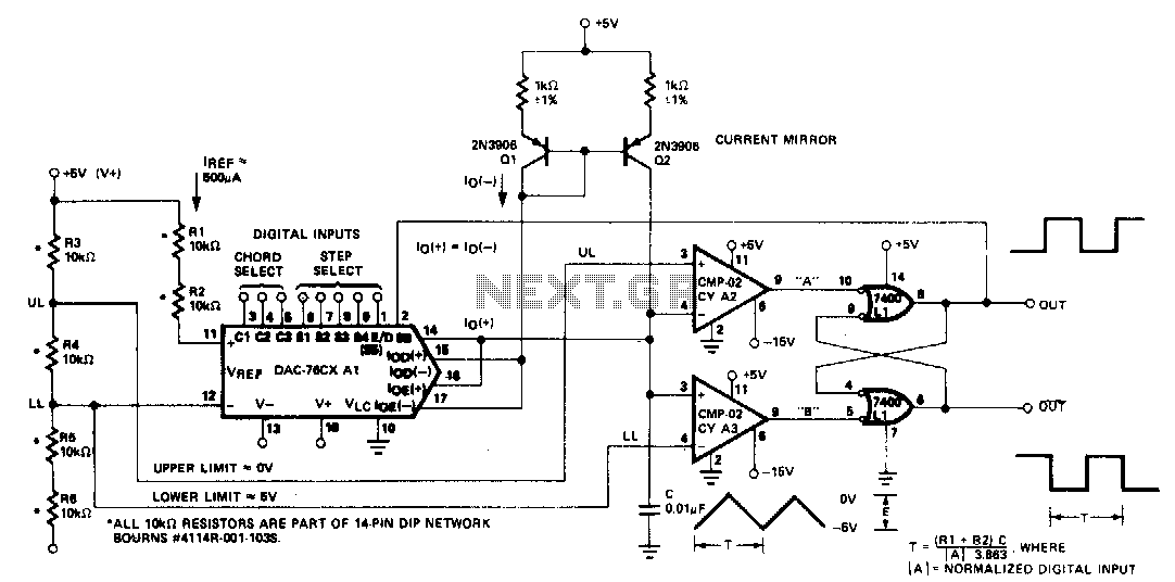
The microprocessor-controlled oscillator has a frequency range of 8159 to 1, covering from 2 Hz to 20 kHz. An exponential, current output integrated circuit digital-to-analog converter (DAC) functions as a programmable current source, alternately charging and discharging a capacitor...
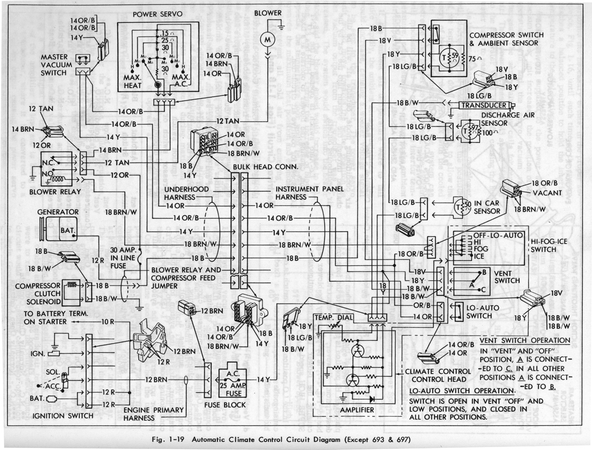
Gerald's 1958 Cadillac Eldorado Seville, 1967 Cadillac Deville, 1967 Eldorado, and 1971 Lincoln Continental Mark III - everything you always wanted to know about these cars. The 1958 Cadillac Eldorado Seville is a classic American luxury vehicle renowned for its...
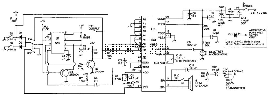
The circuit utilizes an ISD1016 audio record/playback chip from Information Storage Devices, Inc. to record and playback messages on demand. While it is primarily designed for use with transmitters, it can also serve as an electronic notepad or similar...
U1 is a 3817 integrated circuit produced by Fairchild Corporation. It is capable of directly driving a display and can operate in both 12-hour and 24-hour formats. Additionally, it can generate a clock sound and activate radios at scheduled...
The metal detector circuit consists of several key components including the probe oscillator, reference oscillator, oscillation signal processor, mixing amplifier, and ammeter PA. The probe oscillator is made up of the oscillating tube VI, exploration coil L1, capacitors C1...
Warning: include(partials/cookie-banner.php): Failed to open stream: Permission denied in /var/www/html/nextgr/view-circuit.php on line 713
Warning: include(): Failed opening 'partials/cookie-banner.php' for inclusion (include_path='.:/usr/share/php') in /var/www/html/nextgr/view-circuit.php on line 713