
LED Dice circuit
The circuit described utilizes a 555 timer IC (IC1) configured in astable mode, generating a continuous square wave output. This output acts as a clock signal for a decade counter IC (IC2), specifically the 4017B, which counts from 0 to 9. The output pin 5 of the 4017B is connected to the reset pin (pin 15), ensuring that the counter resets after reaching the sixth output (output 6). This configuration effectively limits the counting to six distinct states, corresponding to the six faces of a die.
The output states of the 4017B are utilized to control a set of six LEDs, arranged in pairs to represent the numbers on a die. Each pair of LEDs is controlled by a transistor (Q1 to Q4), which acts as a switch. The transistors are driven by the outputs of the 4017B, with diodes placed in parallel to prevent backfeeding and potential short circuits when multiple outputs are activated simultaneously.
To enable or disable the counter advancement, pin 13 (INHIBIT) of the 4017B is connected to the positive supply through a 100K resistor. This configuration keeps the counter inactive until the START button (S1) is pressed, which connects pin 13 to ground (0V), allowing the counter to begin counting.
The circuit can be powered by a 9V battery or an external power supply ranging from 9V to 12V, providing flexibility in power source selection. The components specified include resistors (R1 to R9) with values ranging from 1K to 100K ohms, capacitors (C1 and C2), and diodes (D1 to D6) for signal routing. The use of red 5mm LEDs (D7 to D13) ensures visibility of the outputs, effectively simulating the random nature of a dice throw. The circuit is designed to be compact, with a 4-pin connector (SL1) facilitating easy connections for the LEDs and other components.The IC1 is a 555 timer IC is connected for, Astable operation the clock pulses are fed to the IC2 via the 10K resistor. The IC2 is a 10 stage counter, output 6 (pin 5) is connected to RESET (pin 15), thus giving us a 6 stage counter , outputs 0 to 5.
The 6 of the LEDs are connected as 3 pairs, thus requiring 4 different signals, these signals come from the 4 transistors, which in turn are connected to the necessary outputs of the IC2. Where a transistor is operated from more than one output, diodes are used to avoid a short circuit situation between outputs.
Pin 13 of the IC2 (INHIBIT) is connected to +ve via a 100K resistor to stop the counter from advancing, however pressing the S1 [START] button will connect pin 13 to 0V line and allow the counter to advance, hence, throwing the dice. The circuit supply can use a 9V battery or external pack 9 until 12V. The D7 until D15 LED?s connected as Fig.2 to make a dice. R1-2=2.2Kohms C1=22uF 25V IC2=4017B R3=10Kohms C2=10nF 100V MKT Q1....4=BC550 R4=100Kohms D1.......6=1N4148 S1=Normal Open Push switch R5.....8=8.2Kohms D7.......13=Red Led 5mm SL1=4pin connector 2.54mm step R9.....5=1Kohms IC1=NE555 or LM555 BATT=9V battery or 12V ext. 🔗 External reference
Related Circuits
The controllable multivibrator, as illustrated in figure 14-40, consists of a 555 timer along with resistors RA, RP1, and capacitor C1. The oscillation frequency is influenced by the control voltage applied to pin 5. This control voltage is determined...
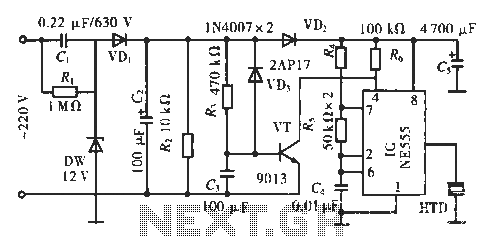
The circuit utilizes a 555 integrated circuit (IC). When an incoming call is received, 220 V AC is stepped down through resistor R1, followed by rectification using diode VD1. A voltage regulator (DW) is employed, and capacitor C2 is...
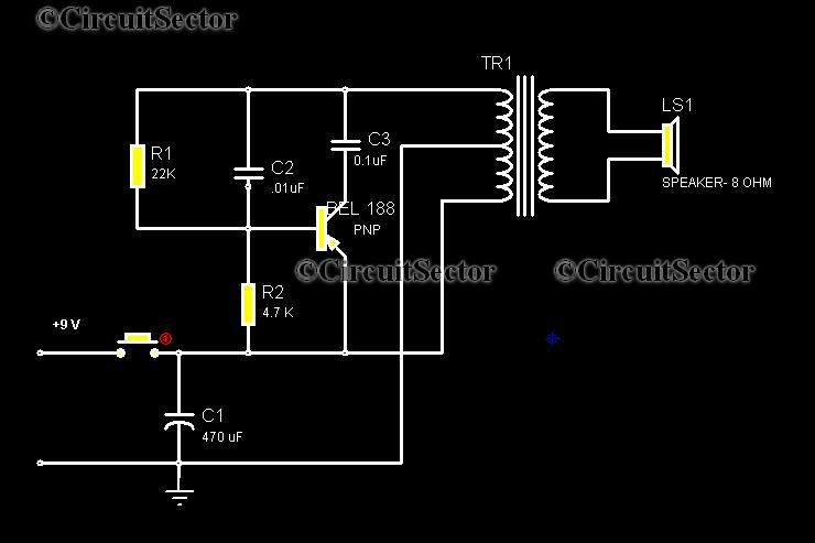
This circuit is a low-cost, one-touch doorbell using a Bel 188 transistor. It is likely one of the most economical bell circuits that can be constructed. The core component of this circuit is the output transformer from a push-pull...
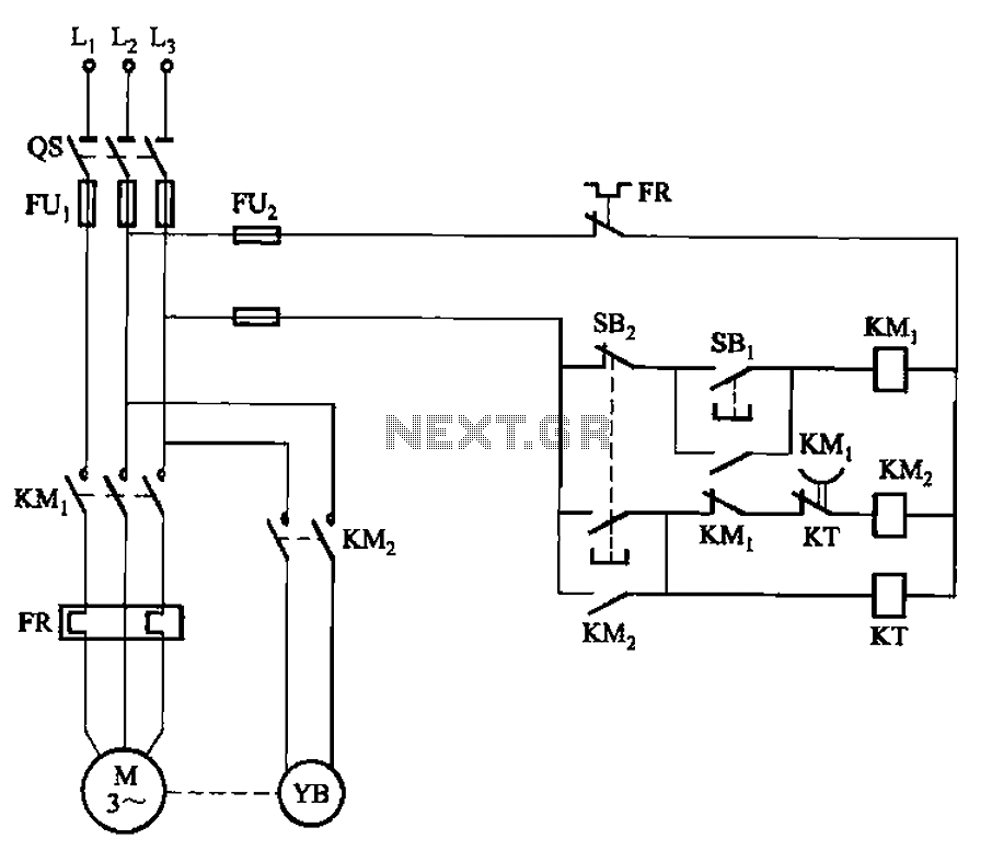
The circuit illustrated in Figure 3-123 operates as follows: When the stop button SBz is pressed, contact KMi releases, cutting off power to the motor. Simultaneously, KMz is activated, engaging the electromagnetic brake YB to hold the motor in...

This is an application circuit for calibration known as a high voltage AC calibrator circuit. An essential aspect of sine wave oscillator design is the stable control of amplitude. This circuit not only stabilizes the amplitude through servo control...
This is a classic frequency divider by two, implemented using a T-flip flop circuit, specifically with IC1 [4011]. In this circuit, the frequency from the network, after limiting the negative half-period of the sine wave and transforming it into...
Warning: include(partials/cookie-banner.php): Failed to open stream: Permission denied in /var/www/html/nextgr/view-circuit.php on line 713
Warning: include(): Failed opening 'partials/cookie-banner.php' for inclusion (include_path='.:/usr/share/php') in /var/www/html/nextgr/view-circuit.php on line 713