
High Voltage AC Calibrator Circuit Using Op Amp

The high voltage AC calibrator circuit is designed to provide precise voltage outputs for calibration purposes, utilizing a combination of feedback mechanisms and amplification stages. The core of the circuit involves a transformer that not only facilitates voltage gain but also plays a crucial role in maintaining a stable amplitude through a servo-controlled feedback loop. The use of a negative absolute value amplifier allows for effective rectification of the feedback signal, ensuring that any discrepancies in output are swiftly corrected.
The LF347 quad operational amplifier is central to the functioning of this circuit. The first two amplifiers work together to produce a rectified feedback signal that is essential for the stability of the amplitude control. The third amplifier in the LF347 quad amplifies the error signal, which is the difference between the feedback and the reference voltage from the LM329. The gain of 100 ensures that even small variations in output are addressed with precision.
The feedback capacitor, rated at 10 µF, is critical in determining the frequency response of the control loop. Its value influences the bandwidth and stability of the circuit, allowing it to maintain a consistent output frequency of 1 kHz. The design ensures that distortion remains below 0.1% at a nominal output of 100 Vrms, which is crucial for high-fidelity applications.
The flexibility of the circuit is enhanced by the option to replace summing resistors with a potentiometer, allowing users to adjust output voltage settings between 3 Vrms and 190 Vrms without affecting the oscillation frequency. This adaptability makes the calibrator suitable for various applications where different voltage levels are required.
Incorporating the DAC1280 D/A converter allows for digital control over the output voltage, providing a modern approach to calibration with three-digit accuracy. This integration facilitates automated systems and enhances the usability of the circuit in digital environments, making it a versatile tool in electronic calibration applications.This a application circuit for calibration. This circuit is called high voltage AC calibrator circuit. In another dimension in sine wave oscillator design is stable control of amplitude. This is the figure of the circuit. In this circuit, not only is the amplitude stabilized by servo control but voltage gain is included within the servo loop. A tr ansformer is used to provide voltage gain within a tightly controlled servo loop. A voltage gain of 100 is achieved by driving the secondary of the transformer and taking the output from the primary. A current sensitive negative absolute value amplifier composed of two amplifiers of an LF347 quad generates a negative rectified feedback signal.
This is compared to the LM329 DC reference at the third LF347 which amplifies the difference at a gain of 100. The 10 F feedback capacitor is used to set the frequency response of the loop. The output of this amplifier controls the amplitude of the LM3900 oscillator thereby closing the loop.
As shown the circuit oscillates at 1 kHz with under 0. 1% distortion for a 100 Vrms (285 Vp-p) output. If the summing resistors from the LM329 are replaced with a potentiometer the loop is stable for output settings ranging from 3 Vrms to 190 Vrms (542 Vp-p!) with no change in frequency. If the DAC1280 D/A converter shown in dashed lines replace the LM329 reference, the AC output voltage can be controlled by the digital code input with 3 digit calibrated accuracy.
[Schematic diagram source: National Semiconductor, Inc] 🔗 External reference
Related Circuits
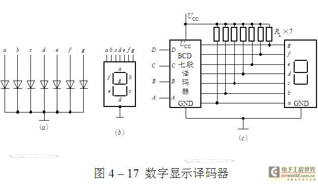
The luminescent diode (LED) is constructed from gallium arsenide (GaAs), a specialized semiconductor material, and gallium arsenide phosphide. It can be used individually or assembled into segment-type or lattice LED display devices. The display unit consists of a sectional...
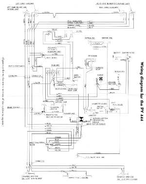
The following circuit illustrates the wiring diagram for the Volvo PV444, a vintage car electrical circuit. It provides an electrical understanding of this uni-body vehicle. The Volvo PV444 wiring diagram serves as a crucial reference for understanding the electrical system...
This circuit is mainly intended to provide common home stereo amplifiers with a microphone input. Using a stereo microphone the circuit must be doubled. In this case, two separate level controls are better than a dual-ganged stereo potentiometer. Low...
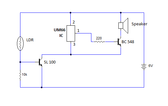
This article provides instructions for creating a light-sensitive morning alarm circuit. The circuit utilizes an LDR (Light Dependent Resistor) or photoresistor to detect morning light, which triggers the alarm section. When light is detected, the circuit produces a melodious...

This simple circuit indicates the status of a phone, including Line OK, Dialing, and Call Attended. It also features a locking mechanism to block outgoing calls while allowing incoming calls, preventing misuse of the telephone. The circuit requires only...
This document outlines the assembly of a circuit designed to pulse width modulate (PWM) a high-power RGB LED strip and program an Arduino to cycle through various colors. The term "high power" refers to a voltage range of 9-12...
Warning: include(partials/cookie-banner.php): Failed to open stream: Permission denied in /var/www/html/nextgr/view-circuit.php on line 713
Warning: include(): Failed opening 'partials/cookie-banner.php' for inclusion (include_path='.:/usr/share/php') in /var/www/html/nextgr/view-circuit.php on line 713