
Wiring the Solar Panels
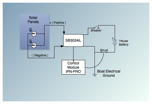
The chosen solution involved drilling a hole in the deck just large enough to fit a 1.5-inch threaded PVC pipe fitting, which was secured by sandwiching the deck between the two halves of the fitting. This created a clean 1.5-inch diameter opening, sealed with 3M 4200. After threading the cables through, there was additional space for 2-3 more cables if needed. For further sealing, butyl rubber can be applied to keep out water while allowing for future maintenance. The cable routing was resolved by using a single hole through the quarter-berth aft bulkhead to guide the cables toward the Blue Sky controller. Another small hole below the controller connected to the battery compartment. Clear water hose was used for chafe protection along the cable path, supplemented with double layers of heavy-duty heat shrink and cable clamps. A 50A circuit breaker was installed for protection of the battery bank and as a power switch for the controller. The cable run to the battery compartment was less than 7 inches, adhering to ABYC standards and protected from chafe with heavy-wall water tubing. The installation of the charge controller involved cutting a hole in the electronics panel, securing the controller, and connecting a digital cable to the SB3024. A twisted pair shielded cable also connected the shunt in the battery compartment to the control module, concluding the solar installation.
The described circuit involves a solar power system integrated into a marine environment, focusing on efficiency, safety, and ease of maintenance. The use of a Blue Sky MPPT solar charge controller ensures optimal charging of the battery bank, maximizing energy harnessed from the solar panels. The implementation of a circuit breaker provides crucial overcurrent protection, safeguarding both the solar charging system and the batteries from potential damage.
The cable routing strategy employed minimizes the risk of water ingress by utilizing a sealed conduit, while the chafe protection measures ensure long-term reliability of the installation. The use of high-quality materials, such as 3M 4200 sealant and heavy-duty heat shrink, further enhances the durability of the connections. The integration of a digital communication line between the charge controller and the battery management system allows for real-time monitoring of battery performance, contributing to efficient energy management.
Overall, this installation exemplifies best practices in marine electrical systems, particularly in the context of renewable energy integration. The meticulous attention to detail in cable management and sealing techniques not only enhances safety but also promotes the longevity of the system, making it a valuable reference for similar projects in marine applications.This is the fifth post in a 5 part series on how I literally saved somewhere between $5, 000 and $9, 000 installing a cockpit arch and a pair of solar panels onto Aletheia, my Allied Princess ketch rigged sailboat. I`ll be posting this series over the next few weeks, so keep checking in for updates. Here is the previous post. The electrical connect ion to the panel really took a lot of thinking before acting, though. Particularly how I was going to get the four heavily-insulated 10-gauge cables through the deck and down below to the Blue Sky MPPT solar charge controller. I decided to take a break and knock out of a few of the pet peeves that I had with the current cockpit arrangement.
As I was cursing the P. O`s choice of sealant on a particularly troublesome and leaky deck fitting, I had a flash of brilliance (this happens roughly 1x10-20 times a year) and decided to borrow PART of his idea - the part that didn`t involve silicone to seal anything, mind. I`ll give you the challenge and see what you come up with before I give you my version of the solution.
The challenge: To get 5 cables of approximately 4mm diameter each through the deck in a clean and orderly fashion, unbroken, but easily removed for maintenance or replacement as the case dictates. The method of traversing the deck itself must be watertight, inexpensive, and involve the least number and smallest size of holes in the deck to accommodate the cables.
The cables are bare at one end, and so may be fed through the deck without the need to accommodate fittings as well, just the cable diameter. And while 4 of the cables are uniform in size, one of them is a flat 2-pair DC cable with a nearly oval cross section rather than round.
Naturally, higher points are given for cleanliness of solution and least amount of redneck engineering (e. g. no utilizing deck vents or locker lids). Chafe must be eliminated at any possible points of contact. Got all that Ready Go! My solution was to drill a hole in the deck just large enough to fit a 1 threaded PVC pipe fitting, and to screw the two halves of the fitting together, sandwiching the deck in between.
This left a nice 1 diameter, clean looking opening in the deck, sealed with 3M 4200. After slipping all of the cables through, I had enough space left to run 2-3 additional cables should I desire to do so. The opening is very small now, and when I wish to seal it further, a simple application of butyl rubber will keep the water out and allow me to remove the cables for maintenance in the future.
The cable routing was a problem that, after some pondering, worked itself out nicely. A single hole through the quarter-berth aft bulkhead lead the cable along the quarter-berth, forward to where I had mounted the Blue Sky. Another small hole below the controller lead to the battery compartment. Application of some clear water hose serves as chafe protection along the cable path, along with double layers of extra-thick heavy duty heatshrink and cable clamps.
A 50A circuit breaker, easily accessible, provides protection for both the battery bank and serves as the controller`s power switch. The run to the battery compartment from there is less than 7 inches in length, within the ABYC standards, and well protected from chafe with heavy-wall water tubing.
Forgive the excessive quantity of photos here, some of you asked for more detail on the cabling, so here it is: Mounting the control module for the charge controller was very straightforward as well: I cut a new hole in my electronics panel, screwed the charge controller in place, and ran the digital cable to the SB3024. Another, twisted pair shielded cable ran from the shunt in the battery compartment (master negative cable) to the control module as well.
And that pretty much concludes the solar installation. Thanks for reading through and I hope this was helpful information to anyone else trying to do it themselves. 🔗 External reference
Related Circuits
Develop a device that operates independently of gasoline, is user-friendly, can serve as a backup energy source, and allows for sharing the construction process with others. The instructional video series is structured similarly to a previous large project that...
A 12 Volt solar power system can provide power to a wide variety of devices. Some examples include: lighting systems, cellular phones, CB and Ham radios, car stereos, televisions, recording equipment, fans, water pumps, and other low voltage DC...
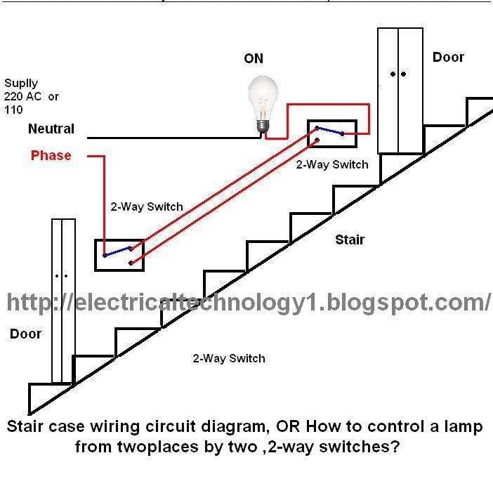
The circuit is complete, and the bulb is ON. To turn OFF the bulb from the upper switch at the top of the stairs, simply turn OFF the switch, which will break the circuit and turn the bulb OFF....

The phase and neutral wires from the power source have already been connected to electrical appliances such as fans and light points. According to the UPS connection diagram, an additional phase wire should be connected to those appliances where...
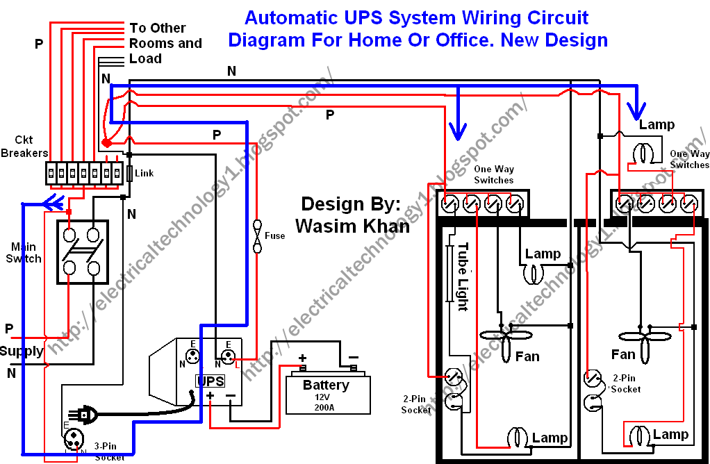
This wiring circuit diagram is designed for providing power to specific rooms in a home or office during a power supply failure. It ensures continuous power supply to devices such as laptops and computers in those particular rooms, especially...
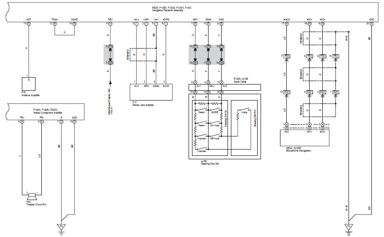
This document contains the wiring diagram for the 2007 Toyota Camry, specifically for the GSV40 and ACV40 series. It details the electrical circuits present in the vehicles, categorizing them by system for clarity. The wiring for each system is...