
Pure Sine-Wave Generator Circuit
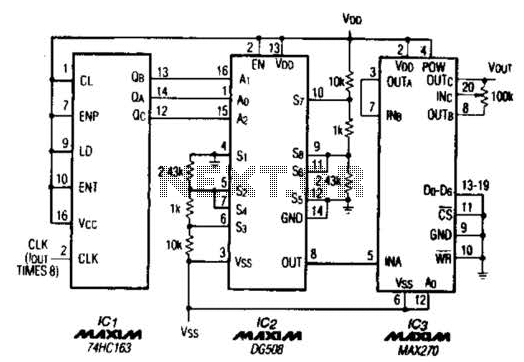
The described circuit is a sophisticated waveform generator capable of producing high-fidelity sine waves with minimal distortion. The integration of a TTL counter allows for precise digital control over the frequency generation process, while the 8-channel analog multiplexer facilitates the selection of different signal paths, enhancing versatility in signal routing.
The fourth-order low-pass filter, constructed from two cascaded Sallen-Key topologies, effectively attenuates unwanted high-frequency components, ensuring that the output sine wave maintains its integrity. The choice of Sallen-Key filters is advantageous due to their simplicity and effectiveness in achieving a flat passband response alongside a sharp roll-off beyond the cutoff frequency.
The cutoff frequency selection mechanism, which utilizes digital inputs to define the frequency range, provides a high level of customization. By connecting the D0 through D6 inputs to either -5 V or ground, the user can select from 128 discrete frequency steps, allowing for precise tuning of the output frequency. This feature is particularly beneficial in applications requiring specific frequency outputs.
The inclusion of a 100 kΩ potentiometer for output level adjustment adds another layer of functionality, enabling the user to fine-tune the amplitude of the generated sine wave. The range of adjustment, from Vw - 1.5 V to Vss + 1.5 V, allows for compatibility with various signal processing stages that may follow the output of this circuit.
Overall, this circuit design represents a robust solution for generating high-quality sine waves, suitable for a variety of applications in signal processing, testing, and other electronic systems requiring precise waveform generation. A TTL counter, an 8-channel analog multiplexer, and a fourth-order low-pass filter can generate 10- to 25-kHz sine waves with a THD better than -80 dB. The circuit cascades the two second-order, continuous-time Sallen-Key filters within ICS to implement the fourth-order low-pass filter.
To operate the circuit, choose the filter`s cutoff frequency,^, by tying IC3`s D0 through D6 inputs to-5 V or ground. The cutoff frequency can be at 128 possible levels between 1 and 25 kHz, depending on those seven digital input levels.Because the circuit ties D0 through D{, to ground Jc equals 1 kHz.
The 100-kQ potentiometer adjusts the output level between Vw - 1.5 V and Vss + 1.5 V. 🔗 External reference
Related Circuits
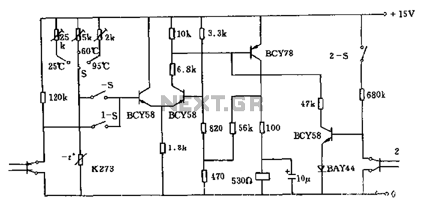
The circuit utilizes a thermistor (K273) to monitor temperature levels and control a relay based on the immersion of two sensor electrodes in a liquid. When the temperature reaches a predetermined threshold, the relay activates to heat the liquid....
This simple water detector circuit utilizes alternating voltage to prevent the corrosion of the electrodes. It is straightforward to construct and employs N1 as a trigger Schmitt gate that generates the AC signal. When an electrical conductor, such as...
The use of a quarter-wave parallel-wire line as a tuning unit has been discussed in the chapter on Short-Lines, where it was pointed out that these circuits have comparatively high Q even at higher frequencies. Their significant length (approximately...
Design a circuit using a power MOSFET to replace the NTC thermistor that many Mag623 users employ to prevent their bulbs from flashing. Although inexpensive and easy to connect, NTCs run quite hot, are affected by ambient temperature, require...
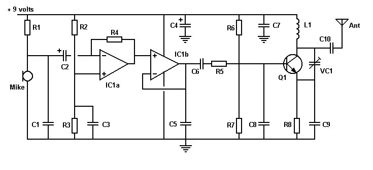
An FM transmitter circuit that utilizes a low power configuration, employing an operational amplifier as an audio preamplifier and a single transistor to function as the RF amplifier. This FM transmitter circuit is designed for low power applications, making...
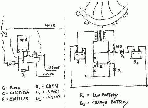
This invention is a back EMF permanent electromagnetic motor generator and method that utilizes a regauging process to capture available electromagnetic energy within the system. The device consists of a rotor equipped with magnets of the same polarity, a...