
LED dimmer circuit
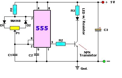
The objective of the project is to design a battery-operated LED dimmer circuit that allows for adjustable brightness levels of LED lights. This circuit typically employs a pulse-width modulation (PWM) technique to control the power delivered to the LED, thus varying its brightness.
The basic components of the circuit include a microcontroller (such as an Arduino or a similar platform), a MOSFET or transistor for switching, a potentiometer for user input, and the LED itself. The microcontroller generates a PWM signal based on the resistance value of the potentiometer, which the user can adjust to set the desired brightness level.
The circuit design should include the following elements:
1. **Power Supply**: A battery pack that provides the necessary voltage and current for the circuit. Common choices include AA batteries or a lithium-ion battery pack, depending on the required operating voltage.
2. **Microcontroller**: A suitable microcontroller that can handle PWM output. The microcontroller should be programmed to read the potentiometer value and adjust the PWM signal accordingly.
3. **Potentiometer**: A variable resistor that allows the user to change the resistance and, consequently, the brightness of the LED. A linear potentiometer is commonly used for this purpose.
4. **Switching Device**: A MOSFET or bipolar junction transistor (BJT) is used to control the current flowing through the LED. The gate or base of the switching device is connected to the PWM output of the microcontroller.
5. **LED**: The light-emitting diode that will be dimmed. The LED should be rated for the voltage used in the circuit, and appropriate current-limiting resistors may be necessary to prevent damage.
6. **Protection Components**: It is advisable to include components such as diodes for flyback protection if inductive loads are involved, and capacitors for smoothing out voltage fluctuations.
The schematic should clearly show the connections between these components, indicating the power supply connections, the PWM output to the MOSFET, and the feedback loop from the potentiometer to the microcontroller. Proper consideration should be given to the ratings of all components to ensure safe and reliable operation of the dimmer circuit.Hi folks. I`m new to the forum and relatively new to diy electronics. My current project involves trying to make a battery-powered LED dimmer circuit. .. 🔗 External reference
Related Circuits
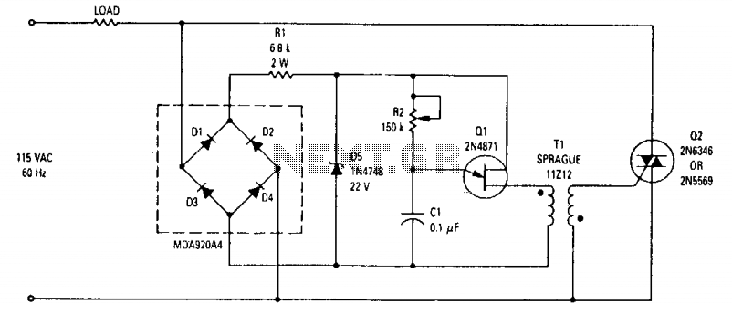
This wide-range light dimmer circuit utilizes a unijunction transistor and a pulse transformer to implement phase control for the TRIAC. The circuit is designed to operate from a 115-volt, 60 Hz power source and can manage up to 800...
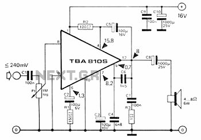
This circuit is a 7 Watt audio amplifier that is simple and easy to construct. It utilizes the TBA810 as the primary component, supported by a few passive components. The amplifier operates effectively, and the necessary kits and components...
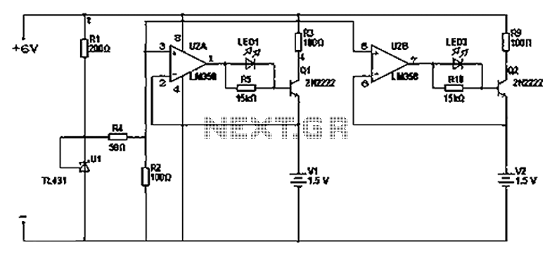
There are two differing opinions regarding the charging of alkaline batteries. Some assert that charging is effective, while others caution against it due to the risk of explosion. It is acknowledged that rechargeable alkaline batteries can typically endure 30...
This is a high-brightness LED driver circuit. To provide a constant-voltage output, DC/DC regulators are typically used. However, a constant-current output is the preferred method for driving LEDs. The high-brightness LED driver circuit is designed to efficiently manage the power...
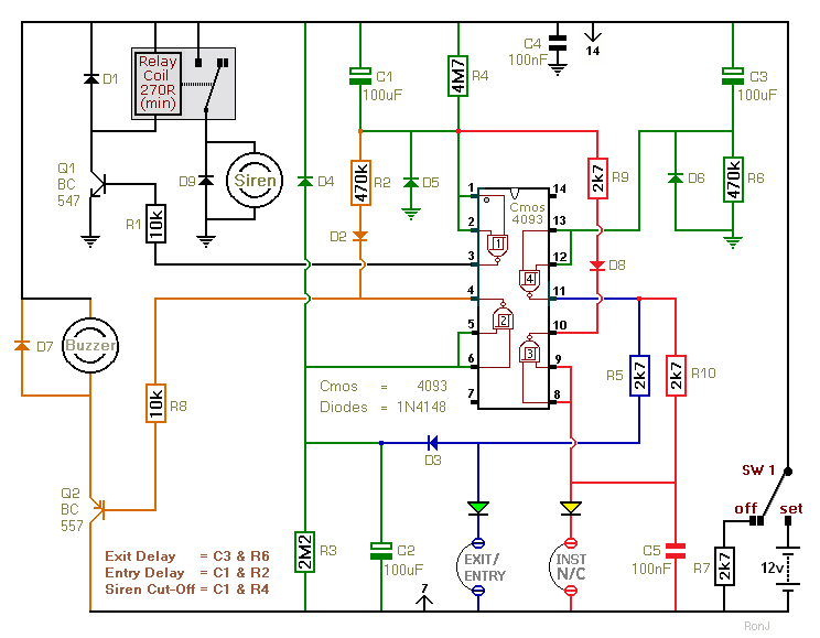
This two-zone alarm features automatic exit, entry, and siren cut-off timers. It was designed for the Beginner's Guide to CMOS Timers, providing a particularly detailed circuit description. An optional One-Time-Only module is available, which will deactivate the siren after...
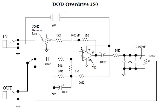
This document provides a circuit diagram for the DOD Overdrive 250 preamp. The DOD Overdrive 250 is similar to the MXR Distortion Plus and several other devices, utilizing a 741 operational amplifier with two diodes on the output channel....
Warning: include(partials/cookie-banner.php): Failed to open stream: Permission denied in /var/www/html/nextgr/view-circuit.php on line 713
Warning: include(): Failed opening 'partials/cookie-banner.php' for inclusion (include_path='.:/usr/share/php') in /var/www/html/nextgr/view-circuit.php on line 713