
LED Emergency Light Circuit With Battery Over Charge Protection
The LED emergency light circuit is designed to ensure reliable operation during power outages while incorporating advanced features for battery management and light control. The heart of the circuit is the IC555 timer, configured in a comparator mode, which monitors the voltage levels to determine the state of the circuit. The use of an LDR (Light Dependent Resistor) allows the circuit to differentiate between day and night conditions. During the day, the high resistance of the LDR keeps the voltage at pin #2 of the IC555 above the threshold, thereby preventing the LEDs from turning on.
The transformer provides the necessary AC voltage, which is rectified to DC for powering the circuit. The configuration of resistors and transistors ensures that the system operates efficiently, with T1 and T2 controlling the flow of current to the LEDs based on the AC mains status. The careful design prevents the LEDs from inadvertently triggering the LDR, which could lead to unwanted switching behavior.
The battery charging mechanism is critical for maintaining the functionality of the emergency light. Transistors T3 and T4, along with the associated components, manage the charging process. When the battery voltage reaches a specified threshold, T3 is activated to allow charging, while T4 is turned off to prevent overcharging. Diode D2 plays a crucial role in directing the charging current and ensuring proper operation of the circuit.
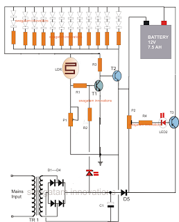
In summary, this LED emergency light circuit is a well-designed solution for providing illumination during power outages, featuring intelligent battery management and light control mechanisms to enhance its reliability and efficiency.The following circuit was designed by me in response to the request sent by PP. The article describes an LED emergency light circuit with advanced features such as, over charge battery cut off, day time auto-disable, and need less to say that the circuit switches ON the LEDs automatically when AC mains fails and reverts to charging mode when power is restored. IC1 which is our very own IC555 has been set as a comparator. During day time, the light over LDR keeps the LDR resistance low such that the potential at pin #2 of the IC is kept well over 1/3Vcc. This situation ensures that the output of the IC at pin #3 stays at logic high. Another factor that keeps T1 switched ON and T2 switched OFF, is the voltage from the transformer power supply stage.
This function is implemented via the resistor R9. This also means that as long as mains AC is available, T2 is restricted from conducting and therefore the LEDs cannot light up. Now suppose the mains power to the transformer fails, and assume that this happens during night or complete darkness, pin#3 of IC555 reverts to zero and also theres no voltage from the power supply, means T1 has absolutely no base bias and therefore has to switch OFF.
This instantly prompts T2 to switch ON and consequently the entire LED array also switches ON, providing the required emergency illumination to the surrounding. MAKE SURE THAT THE LIGHT FROM THE LED DOES NOT FALL OVER THE LDR, WHICH MIGHT TRIGGER A RAPID UNDESIRABLESWITCHINGOF THE LEDS.
Thebatterycharging section consists of T3, T4 and the associated parts. P1 is set such that it switches ON T3 when the battery voltage reaches just above 14 volts. The moment this happens, T4 switches OFF, cutting of the negative supply to the battery and restricting any further charging of the battery. Diode D2 ensures that the battery receives the negative supply during the charging process only through T4 and also provides a normal negative path to to T2 and the LED array when they conduct.
🔗 External reference
Related Circuits

Phase noise is a critical performance parameter of frequency synthesizers for wireless applications. RF system designers of phase-modulated cellular systems, such as PHS, GSM, and IS-54, require low noise local oscillator (L.O.) or frequency synthesizer blocks. This document describes...
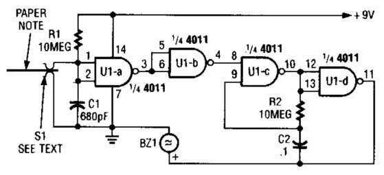
This device prevents paper notes and memos from being overlooked. A paper note placed between two fingers made of a conducting material (metal or conductive plastic) breaks the circuit, allowing pair 1 of Ul-a to go high. The goal...
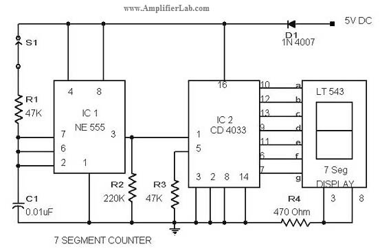
The circuit diagram of a 7-segment counter circuit has been published here. This circuit consists of the counter IC CD4033 as its central component. The 7-segment counter circuit utilizing the CD4033 integrated circuit (IC) is designed to display decimal digits...
The circuit allows up to eight participants, each assigned a unique number from 1 to 8. The display indicates the number of the contestant who presses their button before the others. Simultaneously, a buzzer sounds. Both the display and...
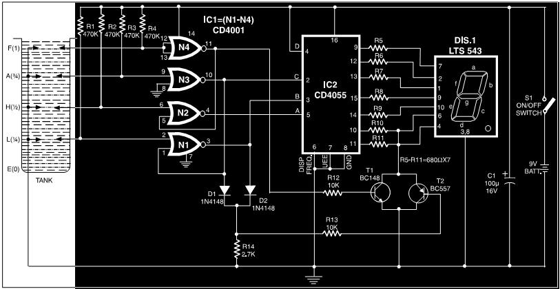
This circuit is a fluid level indicator that displays each level using meaningful English letters. It employs a seven-segment display to represent the letters E for empty, L for low, H for half, A for above average, and F...
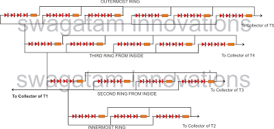
The following article outlines a sophisticated LED sequencing and diverging ring light that can serve as a tail brake light in vehicles. This circuit concept was proposed by a dedicated reader, Mr. Bobby. The design aims to create a...
Warning: include(partials/cookie-banner.php): Failed to open stream: Permission denied in /var/www/html/nextgr/view-circuit.php on line 713
Warning: include(): Failed opening 'partials/cookie-banner.php' for inclusion (include_path='.:/usr/share/php') in /var/www/html/nextgr/view-circuit.php on line 713