
Led flasher
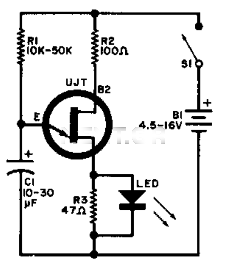
The relaxation oscillator circuit operates by leveraging the charging and discharging characteristics of the capacitor C1. Initially, when power is supplied, C1 starts to charge through the resistor R1, which provides a gradual increase in voltage across the capacitor. Once the voltage across C1 reaches a certain threshold, the UJT (2N4871) is triggered into conduction. This conduction path allows C1 to discharge rapidly through resistor R3 and the LED, resulting in a brief flash of light emitted by the LED.
The time constant of the charging phase, dictated by the values of R1 and C1, plays a crucial role in determining the frequency of the LED flashes. A larger resistor R1 or a larger capacitor C1 will increase the time constant, leading to a slower charging rate and a lower flashing frequency. Conversely, reducing R1 or C1 will decrease the time constant, resulting in a faster flashing rate.
The UJT itself operates in a unique manner, characterized by its negative resistance region, which is essential for sustaining oscillations in the circuit. The 2N4871 UJT is specifically designed for such applications, providing reliable switching performance and stability in the oscillation frequency.
In summary, the relaxation oscillator circuit designed with the UJT 2N4871 effectively utilizes the charging and discharging of capacitor C1 to create a visually appealing LED flashing effect. The design parameters, including the values of R1, R3, and C1, can be adjusted to modify the flashing rate, allowing for customization based on specific application requirements.A relaxation oscillator is used to flash an LED in the base circuit. Cl is charged slowly through R1 by the power source, then discharged periodically through R3 and the LED by the UJT. Flashing rate is determined by the supply voltage and by Rl-Cl's time constant. UJT = 2N4871 🔗 External reference
Related Circuits
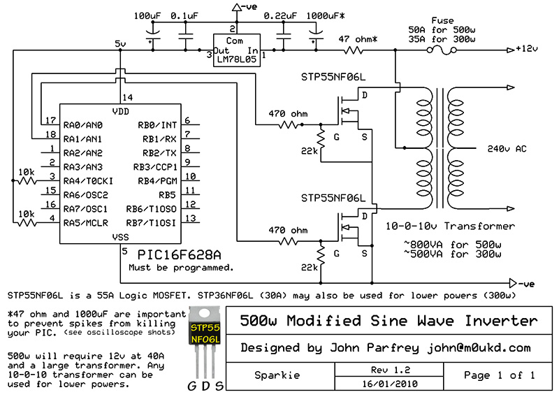
PIC controlled 500W Modified Sine Wave Inverter. The PIC16F628A is programmed to produce a logic 5V signal for 5ms at pin 17, followed by 15ms off. The described circuit implements a 500W modified sine wave inverter controlled by a PIC16F628A...
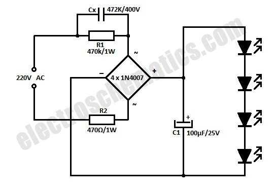
This is a simplified version of a white LED lamp that can be powered directly from the mains. It provides sufficient illumination for reading purposes. Capacitor Cx along... The circuit for the white LED lamp consists of several key components...
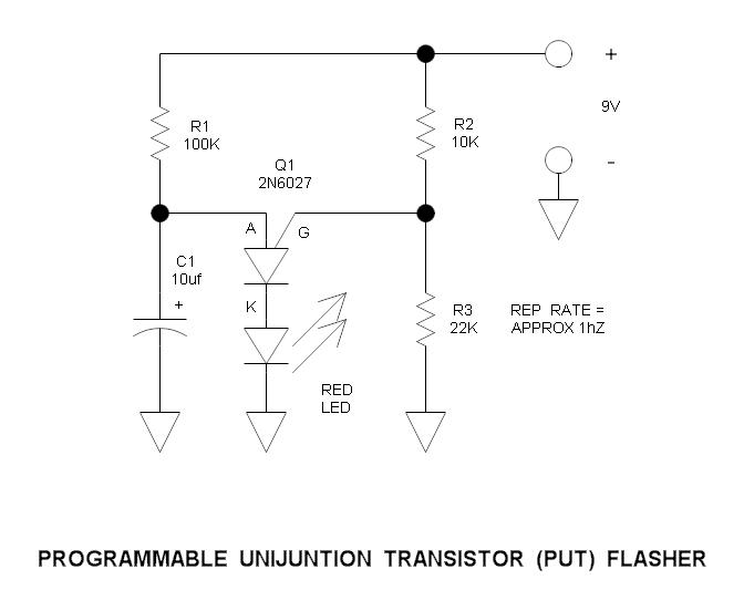
This is a simple circuit that illustrates the function of the programmable unijunction transistor. It can be quickly wired on a proto-board. The circuit utilizes a programmable unijunction transistor (PUT) to demonstrate its operation as an oscillator. The PUT, which...
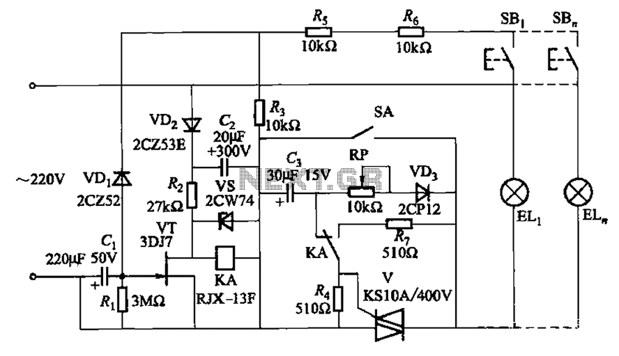
The circuit illustrated in Figure 2-50 utilizes a field effect tube and a combination of electronic components to create a unique self-lighting controller. The working lamp remains illuminated at a reduced brightness rather than being completely turned off, which...

This is a compact LED flasher circuit designed using the 555 timer integrated circuit (IC), powered by two 1.5V batteries. The circuit can function as a flashing metronome, dark room timer, reminder, or for other similar applications. In the...
This circuit uses the effect of a FET as the power to act through the gate with the source to connect. The voltage may vary between 4V and 30V, the current through the LED should constantly be around 15mA....