
LED Flasher

This flashing LED indicator circuit is designed to provide a visual signal using two light-emitting diodes (LEDs) that alternate in illumination. The core component of this circuit is a low-frequency oscillator, which can be implemented using various methods, such as a 555 timer IC configured in astable mode, or a simple transistor-based oscillator circuit.
In the astable configuration of the 555 timer, the circuit consists of two resistors and a capacitor that determine the frequency of oscillation. The output pin of the 555 timer alternates between high and low states, causing the connected LEDs to switch on and off at a predetermined rate. The frequency can be adjusted by changing the values of the resistors and capacitor, allowing for customization of the flashing speed.
The two LEDs are connected in such a way that when one LED is on, the other is off, and vice versa. This is typically achieved by using a complementary transistor pair or an H-bridge configuration that allows for the control of the LEDs based on the output from the oscillator.
Power for the circuit can be supplied from a low-voltage source, such as a battery or a regulated power supply, making this design suitable for portable applications. The simplicity of the circuit also allows for easy assembly and troubleshooting, making it an ideal project for both beginners and experienced electronics enthusiasts.
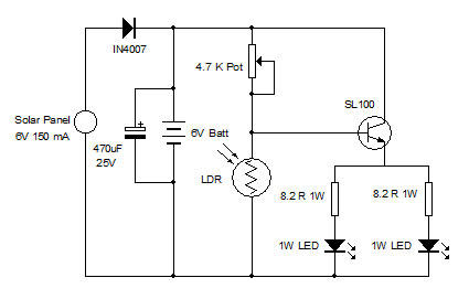
In summary, this economical flashing LED indicator circuit effectively utilizes a low-frequency oscillator to create a visually engaging signal through the alternating illumination of two LEDs, offering versatility and ease of use in various applications.The idea behind this economical ?ashing LED indicator is very simple: it uses a very low frequency oscillator to drive two LEDs. As can be seen in the cir.. 🔗 External reference
Related Circuits

The circuit diagram illustrates a super bright LED night lamp that operates from the mains supply. A bridge rectifier (D1) is employed to convert the AC mains voltage into DC. The combination of capacitor (C1) and resistor (R1) forms...

This circuit utilizes the SSM2044 integrated circuit (IC), which is a four-pole voltage-controlled filter specifically designed for electronic music applications. The on-chip voltage control of resonance facilitates straightforward interfacing with programmers and controllers. The IC is characterized by an...
In various industrial processes, it is essential to rotate a DC (or AC) motor both forward and reverse for a specified duration. Initially, the motor rotates forward (clockwise) for a certain period (approximately 2 to 3 minutes), then stops...

This circuit utilizes two 4516 integrated circuits (ICs) to simulate a game involving two dice. A switch is included to select whether one or two dice will be activated with each press. A 9-volt battery is sufficient for power...

This circuit operates two LED strips in pulsing mode, where one LED strip transitions from an off state to gradually lighting up, then dimming, while the other LED strip performs the opposite action. Each strip can consist of 2...

A Direct-Coupled 6V6 Tube Amplifier with Cathode Follower by Raymond H. Bates from Radio & Television News magazine, November 1949. The Direct-Coupled 6V6 Tube Amplifier is designed to utilize a 6V6 vacuum tube, which is known for its warm sound...