
LED Flasher
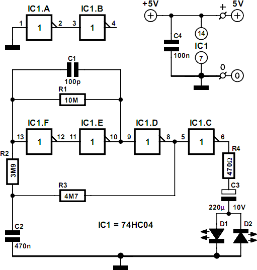
The circuit consists of a low-frequency oscillator driving two LEDs in an anti-parallel configuration, which results in alternating illumination. The use of a large capacitor (C3) in series with the LEDs allows for a brief current flow during each level change, providing a flashing effect. The inclusion of resistors, particularly R4, is critical for limiting the current through the LEDs to a safe level, ensuring longevity and reliability. The calculated peak currents indicate that the design is optimized for low-current red LEDs, which are known for their efficiency.
The operational characteristics of the circuit are influenced by the values of capacitors C1 and C2, which affect the timing and frequency of the LED flashes. The circuit's design allows for adjustments to be made easily by varying the capacitance of C2, thus enabling customization of the flash rate. The choice of using a Schmitt-trigger inverter, such as the 74HC14, enhances the stability of the oscillator, contributing to consistent performance.
In summary, this economical flashing LED indicator circuit is designed to provide a visually effective signaling mechanism with minimal power consumption. The dual LED configuration not only improves efficiency but also enhances the visual output, making it suitable for various applications where low power and clear signaling are essential.The idea behind this economical‚ ashing LED indicator is very simple. It uses a very low frequency oscillator to drive two LEDs. As can be seen in the circuit diagram, the LEDs are connected in anti-parallel. At every change in level there will only be a current ¬‚ow for a short time, due to the large capacitor (C3) that is connected in series with D1 and D2. When C3 is charging D1 lights up and when it is discharging D2 lights up. The current through the LEDs is limited by R4. When the circuit is switched on the peak current is determined by R4 and for a red LED will be just over 7 mA: (5 1. 6) / 470 = 7. 2 mA. This value has been chosen because it is the maximum safe current for certain types of low-current LEDs.
When the circuit is in operation the (dis)charging of C1 determines the maximum current. The electrolytic has a minimum voltage remaining which is equal to the LED voltage, causing the pulses to be smaller than the very ¬rst pulse: (5 2 G— 1. 6) / 470 = 3. 8 mA peak. If one LED is sufficient then you can replace either D1 or D2 with a Schottky diode; the pulse through the remaining LED then becomes slightly larger.
The use of two LEDs has the advantage that the discharge current of C3 is also used by the indicator, which makes the circuit more efficient. The oscillator can of course be replaced by a different type, for example the classic Schmitt-trigger/inverter type using a 74HC14 and RC network.
The version used here has the advantage of offering a better stability. C1 makes IC1f switch faster. The resistors have been made as large as possible, so the adjustment of the ¬‚ash frequency is best done by varying the value of C2. The period with the component values given is about 6 seconds, so a LED will ¬‚ash every 3 seconds. The current consumption is determined mainly by IC1f, since this is almost working as a linear ampli ¬er.
The circuit doesn`t draw more than about 1. 3 mA in total. The LEDs used should preferably be red low-current` or high-efficiency` types. The current pulses will then be slightly larger and the efficiency of red LEDs is still better than that of green or yellow ones. 🔗 External reference
Related Circuits
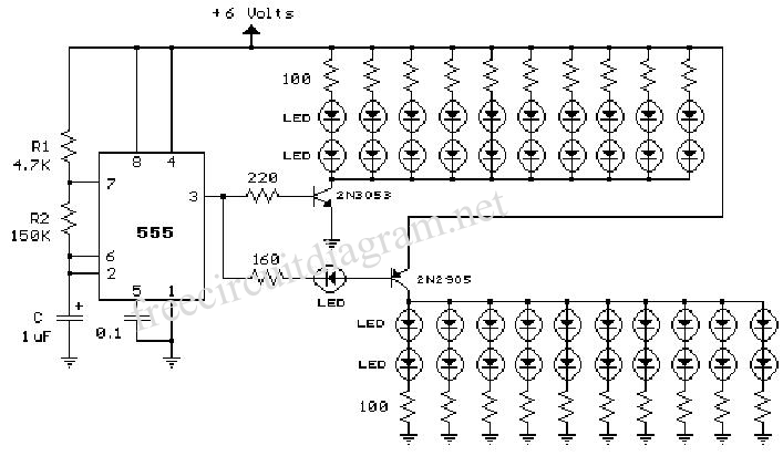
The 555 circuit described is a flashing bicycle light powered by four C, D, or AA cells (6 volts). It features two sets of 20 LEDs that flash alternately at approximately 4.7 cycles per second, utilizing the specified RC...
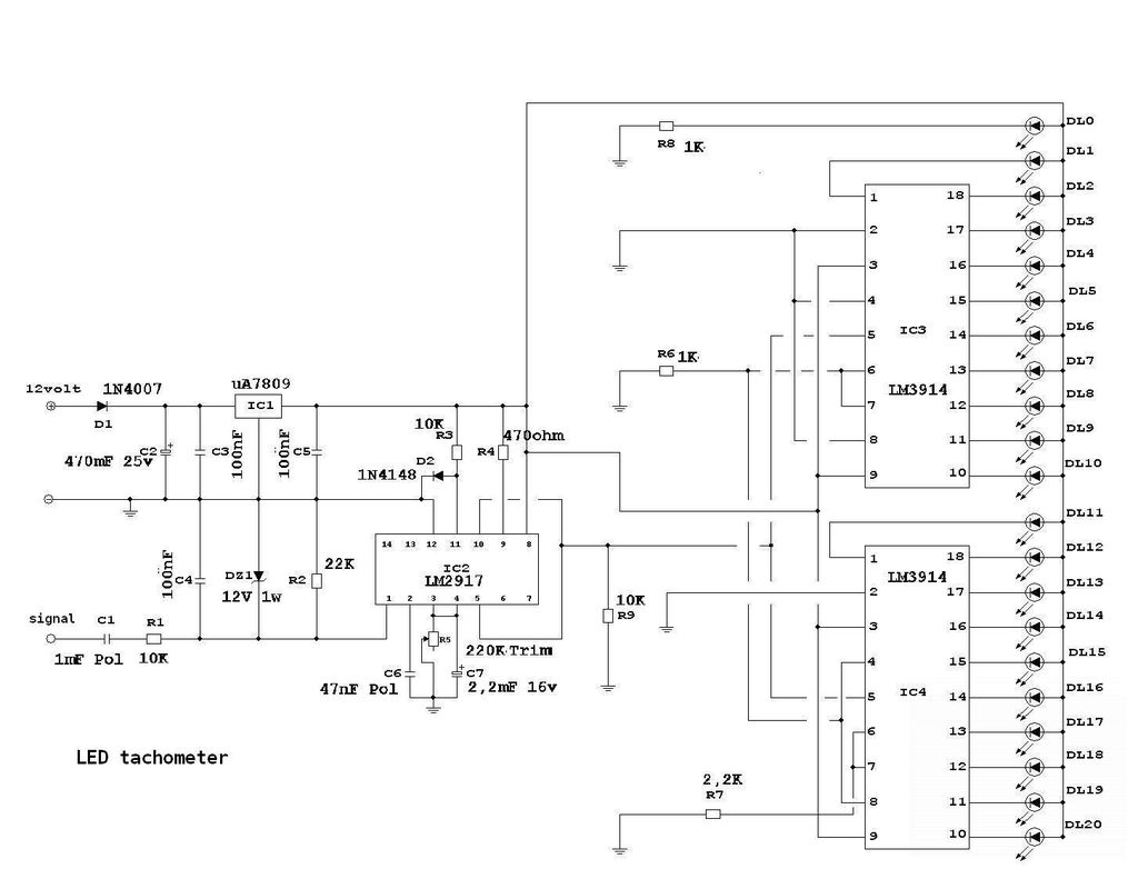
Each unit can drive 10 LEDs in either bar mode or dot mode, with the ability to switch between both modes as detailed in the datasheet. The setup accommodates 21 LEDs of any color, with bright white LEDs being...
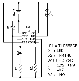
This circuit utilizes the TLC555CP timer integrated circuit to flash an LED approximately twice per second. This specific 555 timer operates on a voltage of only 3 volts, allowing it to be powered by two 1.5-volt cells. When using...
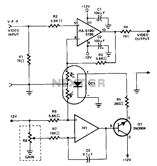
This amplifier utilizes a cascaded operational amplifier (op amp) integrator and a transistor buffer, Q1, to drive the gain control element. With a minor modification, the HA-5190/5195 stage is configured as a conventional non-inverting op amp and includes input...
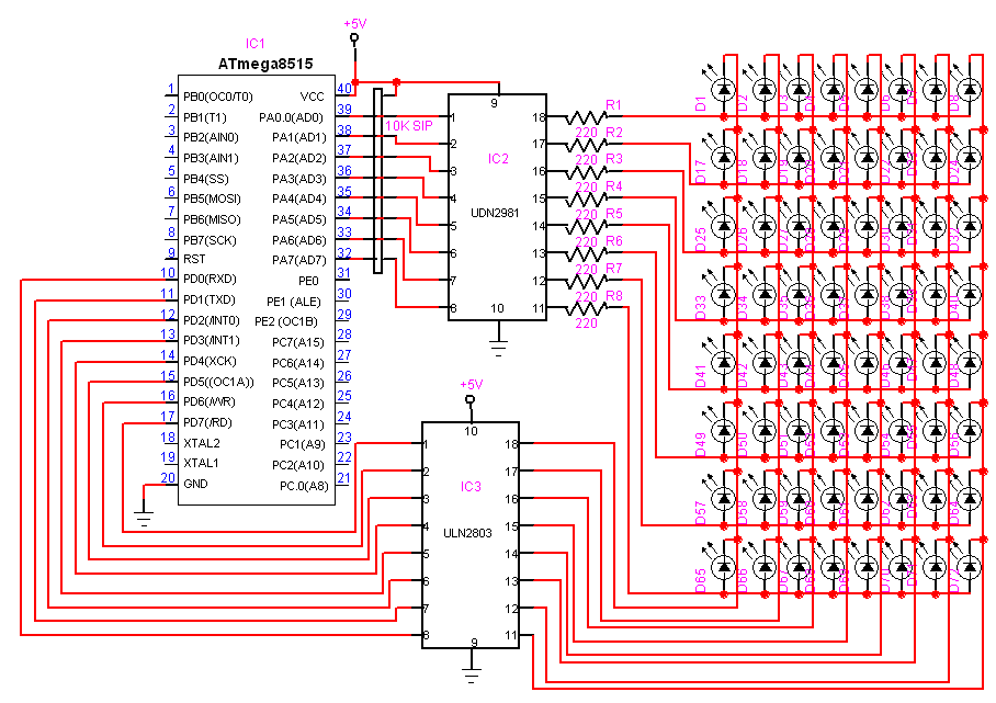
Here is another project that creates a scrolling LED display. This display consists of 64 LEDs arranged in a matrix configuration. The anodes are driven through a driver circuit. The scrolling LED display project utilizes a matrix of 64 LEDs,...
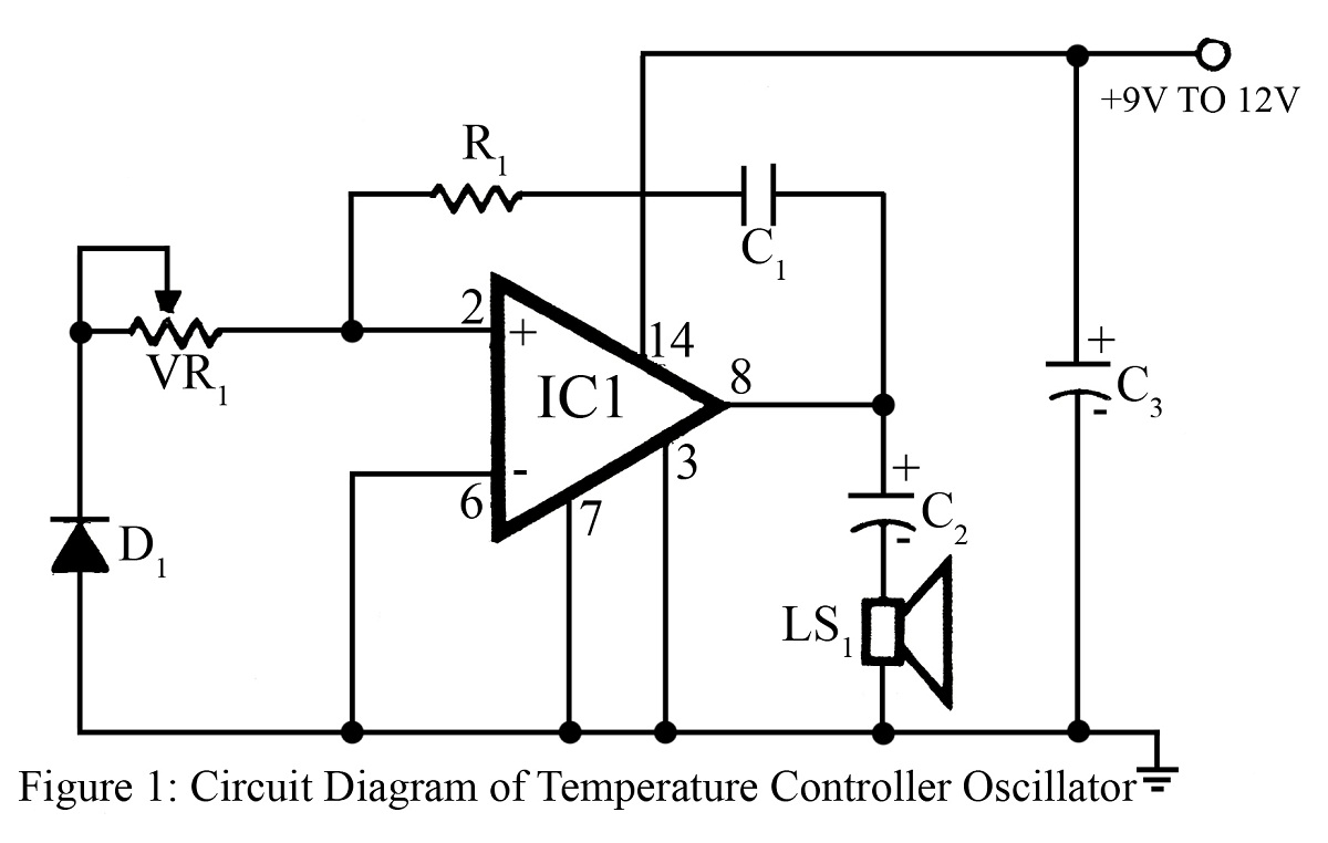
The output frequency or tone of this oscillator circuit varies with the temperature at which the input germanium diode is maintained. The reverse resistance of D1 ranges from 500 ohms to 10 k ohms when the temperature fluctuates between...
Warning: include(partials/cookie-banner.php): Failed to open stream: Permission denied in /var/www/html/nextgr/view-circuit.php on line 713
Warning: include(): Failed opening 'partials/cookie-banner.php' for inclusion (include_path='.:/usr/share/php') in /var/www/html/nextgr/view-circuit.php on line 713