
Led flasher IIV
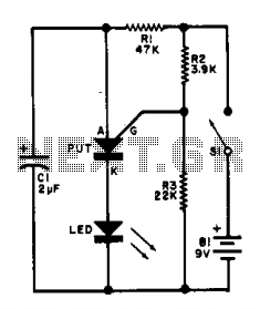
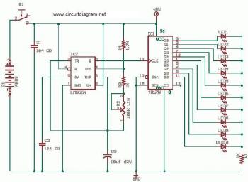
The flasher circuit utilizes a relaxation oscillator configuration, which is characterized by the repeated charging and discharging of a capacitor to create a square wave output. In this design, the PUT acts as the switching element that controls the discharge of capacitor C1 through the LED, resulting in the LED flashing at a defined rate.
The circuit typically includes a resistor connected to the capacitor C1, which, along with the PUT, determines the timing characteristics of the oscillator. When the circuit is powered, C1 begins to charge through the resistor until it reaches a threshold voltage that triggers the PUT to conduct. Upon conduction, the stored charge in C1 is rapidly discharged through the LED, causing it to illuminate. As the capacitor discharges, the voltage across it drops, eventually turning off the PUT and allowing C1 to recharge, thus repeating the cycle.
The component values, including the resistance and capacitance, play a crucial role in defining the flashing rate. For a flashing rate of approximately 100 flashes per minute, appropriate resistor and capacitor values must be selected. The relationship between these components can be expressed through the time constant formula, which calculates the time it takes for the capacitor to charge or discharge to a certain percentage of the supply voltage.
In summary, this flasher circuit exemplifies a simple yet effective application of a relaxation oscillator using a PUT, enabling a visually engaging LED flashing effect at a consistent rate determined by the chosen component values.This flasher circuit operates as a relaxation oscillator with Cl discharged periodically through the LED as the PUT switches on. The flashing rate is about 100/minute with the component values listed. 🔗 External reference
Related Circuits

This is a circuit design for a digital voltmeter with an LED display. It is suitable for measuring the output voltage of a DC power supply. The circuit features a 3.5-digit LED display with a negative voltage indicator and...
This page outlines the hardware and software design of a printer power switch that is controlled via USB from a Linksys NSLU2, also referred to as Slug. Although primarily designed for printer control, the unit can manage any device...
This is a straightforward and effective LED circuit that can be powered directly from an AC mains supply ranging from 100 volts to 230 volts. The circuit can serve as a mains power indicator or a night lamp. Resistors...
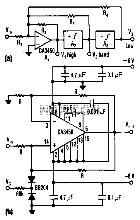
The control voltage Vc effectively adjusts the cutoff frequency w0 of this state-variable filter to any desired value, ranging from approximately 1.7 MHz to 5 MHz, using a BB 204 varicap and a resistance of 100 kΩ. Vc can...
In conventional white LED design, the Max1916 low-dropout bias supply for white LEDs serves as a high-performance alternative to simple ballast resistors. The Max1916 is an integrated circuit designed to provide a stable and efficient bias supply for white LEDs....
This is a doorbell circuit featuring flashing LEDs for enhanced visual appeal. The NE555 integrated circuit (IC1) functions as a clock generator, configured as an astable multivibrator with a frequency adjustable via a potentiometer (VR1). The clock pulses generated...