
LED Flasher Schematic

The flasher circuit utilizes the 555 timer in astable mode, which allows it to continuously oscillate between high and low states, creating a flashing effect. The frequency of the oscillation is determined by the resistors R1 and R2, along with the capacitor C1. The relationship between these components can be expressed through the formula for frequency (f) in an astable configuration:
\[ f = \frac{1.44}{(R1 + 2R2) \cdot C1} \]
In this case, R1 and R2 are adjustable to achieve the desired flash rate. The duty cycle, which describes the proportion of time the output is high versus low, can also be modified by varying R1 and R2. A typical configuration may yield a duty cycle of approximately 33% for R1 and R2 values that maintain a balance between the two resistances.
The power transistor, rated for 10A, acts as a switch to control the load connected to the output of the 555 timer. This high rating ensures that the transistor can handle significant current without overheating, which may be beneficial depending on the application. However, it is essential to ensure that the transistor is appropriately biased and that a suitable base resistor is used to limit the current flowing into the base of the transistor.
Capacitor C2 serves as a bypass capacitor, which helps filter out any high-frequency noise that may affect the operation of the timer. While not strictly necessary, including C2 can improve the stability of the circuit. The choice of C1 is crucial; a ceramic capacitor is preferred due to its stability and low equivalent series resistance (ESR). When using tantalum or electrolytic capacitors, it is imperative to observe the correct polarity to avoid catastrophic failure, as these types of capacitors are polarized.
Overall, this flasher circuit is a versatile design that can be adapted to various applications, including decorative lighting, signaling devices, or other visual indicators. Proper component selection and configuration will ensure reliable performance and safety.Here`s the new flasher circuit schematic. It consists of a 555 timer circuit and a power transistor. The power transistor is probably way overkill, (it is rated at 10A) but it`s what I had available. You can vary C1, R1 and R2 for to vary the flash rate and duty cycle. For the R and C values shown, then flash rate is about 1. 4 Hz (which is about 8 5 flashes per minute). There is a ton of information about the 555 timer on the web, including programs that will calculate the R and C values for you. Depending on the type of components that you choose, the R and C values can vary by 10% or more, so you may need to tweak some values.
C2 should be a ceramic bypass cap, but it does not appear to be essential, my circuit worked fine either with or without C2. C1 should be a ceramic cap, but if you decide to use a tantalum or electrolytic cap for C1, then make sure that you install it in the correct polarity, or it could explode.
If you have any doubts about your electronics capabilities, then you should not build this circuit. 🔗 External reference
Related Circuits
White LEDs have a rated current at a voltage drop of about 3.3 to 3.4 V. It is ideal to be powered from the battery voltage which is slightly larger. Then there is the best energy used. In this...
This circuit illustrates the TDA1054 tone control stereo preamplifier circuit diagram. Features include the National Semiconductor LM35 integrated circuit, which utilizes semiconductor technology. The TDA1054 is a versatile integrated circuit designed for use in audio applications, particularly in tone control...

The master mode selection switch is IC6, which controls the four mode LEDs that correspond to the measured units: kHz, counts, milliseconds, or seconds. In standard frequency counter mode (mode 0, unit: kHz) and counter mode (mode 1, unit:...

This project demonstrates the construction of a simple flashing light circuit using the IC 555 timer. The 555 timer functions as a clock generator with a duty cycle of less than 100% and greater than 50%. Additional components include...
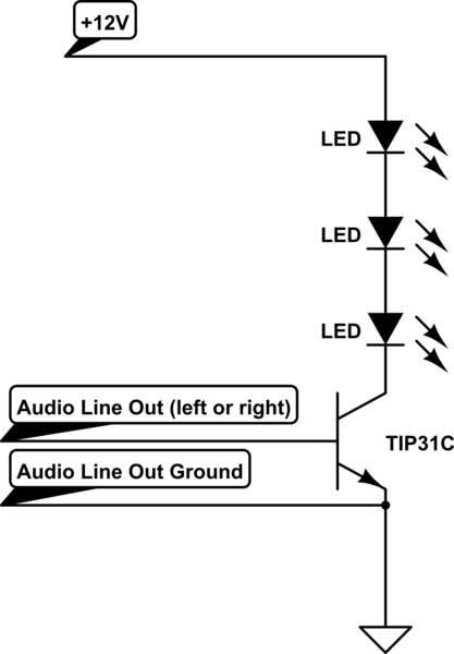
A circuit connects the line output (audio output) of a music-playing device to a large strip of approximately 200 LEDs, allowing them to flash in sync with the music. The circuit functions effectively when using a laptop as the...
This indicator shows through a dual-LED see if a fuse is intact. The module is designed for 230 V AC. The green LED illuminates when the fuse is still good, the red lights when the fuse is broken. Perhaps...