
led interface with microcontroller
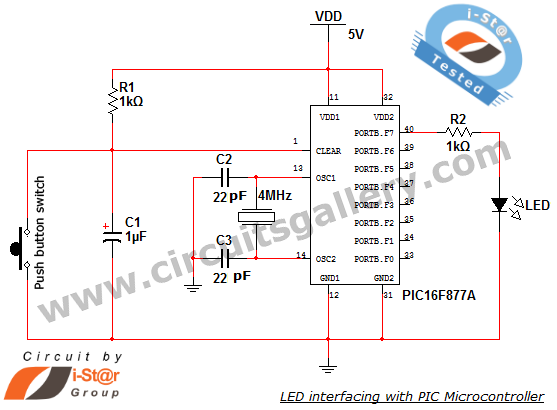
To interface an LED with a PIC microcontroller, the following steps outline the necessary components and connections. The PIC 16F877A microcontroller is equipped with multiple I/O ports, which can be configured to control the LED. The LED should be connected in series with a current-limiting resistor to prevent excessive current flow, which could damage the LED. A common choice for the resistor value is 220 ohms to 1k ohm, depending on the supply voltage and the specifications of the LED.
The circuit can be set up as follows: connect the anode (positive terminal) of the LED to one of the microcontroller's digital output pins, such as PORTB0. The cathode (negative terminal) should be connected to ground through the resistor. This configuration allows the microcontroller to control the LED by sending a HIGH signal to turn it on and a LOW signal to turn it off.
In the embedded program, the configuration of the microcontroller's ports must be initialized to set the designated pin as an output. The program will typically include a loop that turns the LED on and off with a specified delay. The delay can easily be adjusted by changing the argument in the delay_ms() function, thus controlling the blinking rate of the LED.
For example, the main loop of the program could look like this:
```c
void main() {
TRISB0 = 0; // Set PORTB0 as output
while(1) {
PORTBbits.RB0 = 1; // Turn LED on
delay_ms(1000); // Wait for 1 second
PORTBbits.RB0 = 0; // Turn LED off
delay_ms(1000); // Wait for 1 second
}
}
```
This simple program demonstrates how to effectively control an LED using a PIC microcontroller, providing a foundational experience for those new to embedded systems. The use of the Micro C compiler streamlines the coding process and enhances accessibility for beginners, making it an ideal choice for educational purposes in microcontroller programming.How to interface LED with Microchip`s PIC microcontroller How to connect LEDs to a PIC microcontroller LED interfacing is the stepping stone for microcontroller development. This is a simple embedded program for PIC 16F877A to interface LEDs, suitable for beginners who wish to study basics of embedded microcontroller programming.
The program is developed through Micro Ccompiler, one of the best solutions for embedded programming in PIC family. It is compatible for Windows XP and Windows 7 platforms and comes with internal burning tools. This PIC circuit is a beginner circuit, do this PIC project to explore the world of microcontrollers.
Provide a delay. The inbuilt delay function, that is delay_ms(); gives some delay. You can change the duration of LED blinking by giving any value to the calling field of this function. For example delay_ms(1000); will give 1 second delay. 🔗 External reference
Related Circuits
The modification of a basic speed control circuit for small DC permanent-magnet motors implements a maximum current limit during normal operating conditions and a reduced current limit during stall conditions. This design aims to limit the dissipation of series...
This is a simple LED flasher using two 2N3904 transistors. Classic astable multivibrator using 2 transistors. Transistor is not critical. Try these: 2N4401, 2N2222, NTE123A, NTE123AP, NTE159, TUP/TUN and those in your junk box, you may find that most...

This simple mock flasher LED simulates the indicator of a sophisticated alarm system. It can be placed in doors, gates, and vehicles to confuse intruders. The mock flasher LED circuit is designed to mimic the flashing behavior of a typical...

Prototype 2 utilizes a common base to control various elements. This iteration includes a button that activates the tone only when pressed, along with a rotary potentiometer for volume adjustment. The circuit incorporates an Analog Devices ADXL3xx accelerometer that...

This is a three-mode lamp dimmer circuit with touch control. This circuit can be used to control a lamp in three operation modes: dim, off, and bright. It utilizes a NE555 timer. The three-mode lamp dimmer circuit designed with touch...
The circuit below illustrates powering one or two LEDs from the 120-volt AC line using a capacitor to drop the voltage and a small resistor to limit the inrush current. Since the capacitor must pass current in both directions,...