
Three-phase controlled rectifier circuit
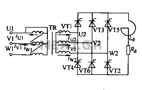
The described trigger circuit encompasses several configurations designed to manipulate electrical signals for various applications, particularly in motor control. The TRIAC serves as a key component, allowing for the regulation of power to the motor based on the phase shift induced by the capacitor. The use of a 30W adjustable potentiometer provides flexibility in controlling the output pulse, enabling fine-tuning of the motor's operational speed.
The integration of flip-flop circuits enhances the versatility of the design, allowing for bidirectional control of the motor, which is essential for applications requiring direction reversal. This setup is particularly useful in robotics or automated systems where precise control over motor functions is necessary.
The choice of components is critical for ensuring reliable operation. The main circuit capacitor, rated at 901 F / 600V, must withstand the voltage and provide adequate phase shift for effective control. The selected VT1 transistor, with a rating of 3CTS20A capable of handling voltages between 800 to 1000V, ensures that the circuit can manage the high power requirements of the motor. The fuses FU1 and FU2, rated at 10A, provide necessary protection against overcurrent conditions, safeguarding the circuit from potential damage.
Overall, this trigger circuit design illustrates a sophisticated approach to motor speed control, combining various electronic components and configurations to achieve desired operational characteristics. The modular nature of the design allows for customization based on specific application needs, making it a valuable solution in the field of electronics.Trigger circuit routing forms, such as some simple trigger circuit, single-junction transistor trigger circuit, synchronous sine wave trigger circuit, sawtooth transition phase shift (synchronous) trigger circuit, integrated trigger circuit. For limited space, this section can only include individual cases for the introduction. Introduction to circuit theory t triggered by a sharp pulse output circuit to trigger the TRIAC, turning it on, the capacitor will be 220V single-phase power phase-shift followed by motor t make it work. 30W adjustment potentiometer output pulse trigger line is changed, thereby changing the VT1 conduction angle change given the magnitude of the voltage stator windings, enabling stepless speed regulation.
The circuit may be two sets of flip-flop circuit, triggering the two bidirectional thyristor achieve electric reversing speed control unit. Component parameters: the main circuit capacitor selected phase shift 901, F / 600V. VT1 election 3CTS20A / 800 ~ 1000V, FU1, FU2 election 10A, the rest of the circuit diagram according to preferences.
Related Circuits
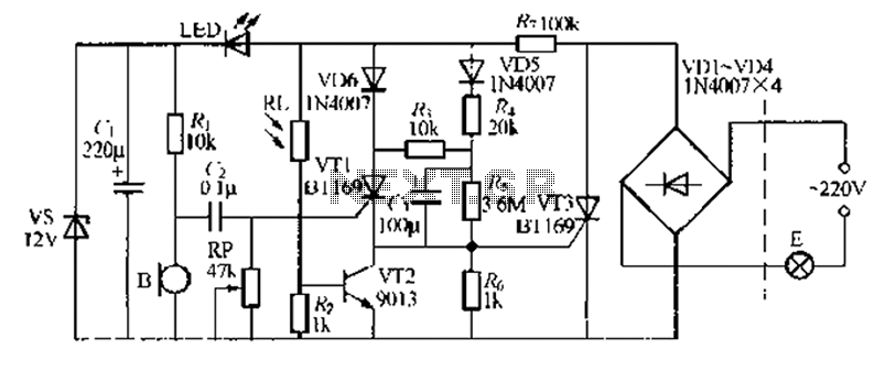
A relatively simple circuit for controlling a stair walkway light with a delay feature. The circuit has a drawback in that the voice activation is somewhat less sensitive, making it sometimes difficult to trigger with general conversation. However, it...
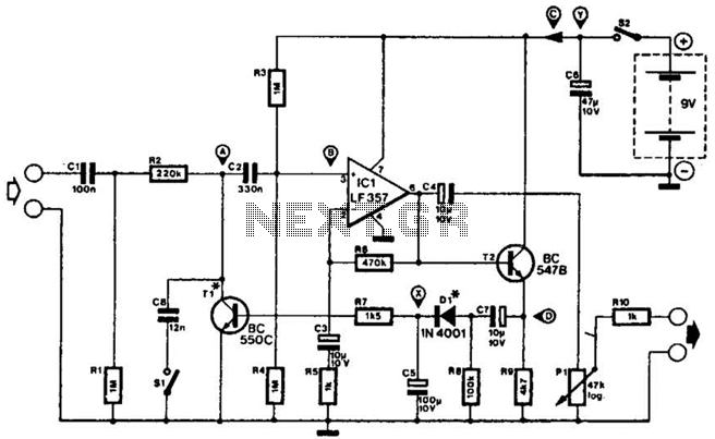
This compressor will compress a 25-mV peak-to-peak (p-p) audio signal to a 20-V p-p output, maintaining input levels between 1.5 V p-p and 3.5 V p-p, with a frequency response ranging from 7 Hz to 67 kHz. It is...
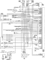
The electrical wiring diagram for the 1993 VW Passat includes the Engine Control Module, Automatic Control Unit, and Automatic Solenoid. This diagram illustrates the connections and wiring between various components of the vehicle's system, such as the multi-function switch,...
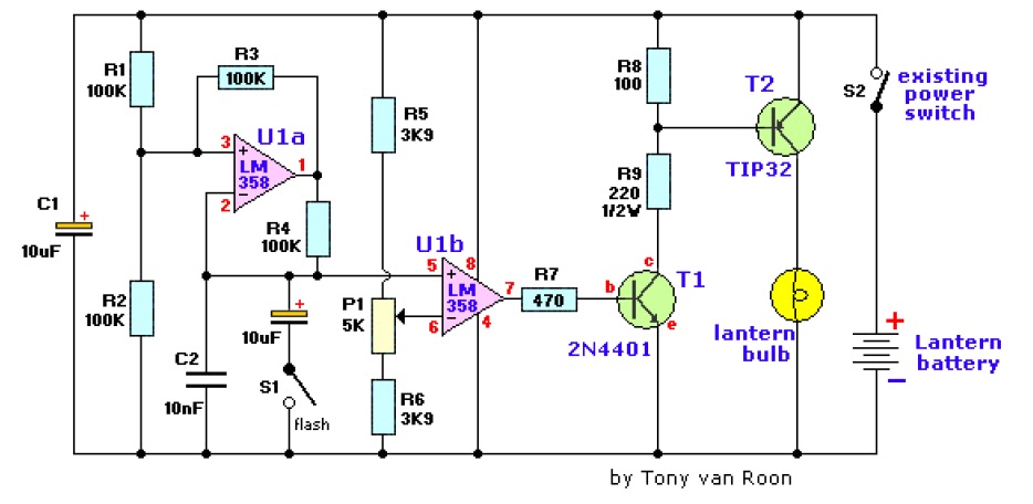
The electronic lantern control circuit enhances an existing battery-powered lantern or flashlight, or can be incorporated into a custom design, by providing high-efficiency dimming and flashing capabilities. This circuit is particularly useful in automotive applications, serving as an effective...
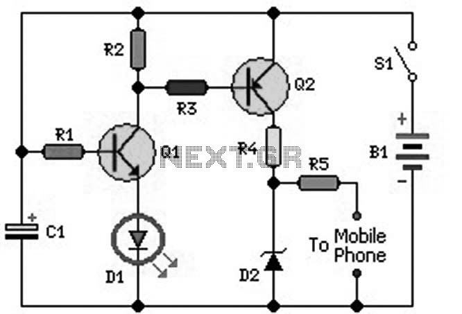
An ideal mobile charger utilizing 1.5-volt pen cells to charge mobile phones while traveling. This charger can replenish a cell phone battery three to four times in locations where AC power is unavailable. Most mobile phone batteries are rated...
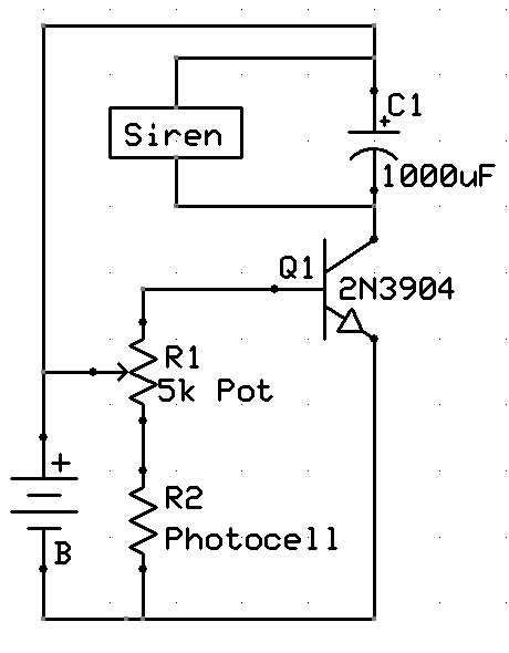
A new user has recently discovered a Laser Alarm System and has decided to explore this project. The Laser Alarm System is a security device that utilizes laser beams to detect unauthorized entry or movement within a designated area. The...