
Long range AM transmitter Using BF495 Transistor

The AM transmitter circuit utilizes three transistors configured to amplify and modulate the input audio signal. The first transistor acts as a microphone preamplifier, converting the audio signal into an electrical signal suitable for further processing. The second transistor functions as a modulator, where the audio signal is combined with a high-frequency carrier wave generated by an oscillator circuit. The third transistor serves as a final amplifier, boosting the modulated signal to a level suitable for transmission.
In this setup, proper tuning of the circuit is crucial for optimal performance. The oscillator frequency must be adjusted to match the desired transmission frequency, while the antenna must be matched to the transmitter's output impedance to maximize radiated power and minimize signal loss. Capacitors and inductors are typically used in the tuning circuit to adjust the frequency response and ensure that the transmitter operates within the appropriate bandwidth.
The circuit may also include additional components such as resistors for biasing the transistors, diodes for signal rectification, and filters to eliminate unwanted harmonics and noise. The overall design must adhere to relevant regulations regarding transmission power and frequency to ensure compliance with communication standards. Proper assembly and layout of the circuit are essential to minimize interference and maintain signal integrity during operation.the circuit diagram of an AM transmitter circuit based on three transistors. With correct tuning and a matching antenna, the transmitter can .. 🔗 External reference
Related Circuits

This is a 6-meter band transmitter RF power amplifier (50 MHz) with a 100W output. It is compatible with the FT-736R and is driven by a 10W signal for 6m SSB DX. The construction information is sourced from Japan...

Here's a circuit that takes advantage of the photo-voltaic voltage of an ordinary LED. The LED voltage is buffered by a junction FET transistor and then applied to the inverting input of an op-amp with a gain of about...
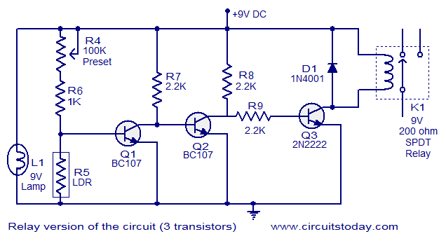
This document describes a simple fire alarm circuit utilizing a Light Dependent Resistor (LDR) and lamp combination for fire detection. The alarm activates by detecting smoke generated during a fire. When smoke is present, the circuit triggers an audible...

The FM transmitter is relatively simple to build and requires only one adjustment, making it ideal for beginners. It is important to clarify that, with wide-band deviation, the Voltage Controlled Oscillator (VCO) is never locked in phase, only in...

As a fully-featured Linux computer, many external programmers can be used with the Raspberry Pi to program the Atmel AVR range of microprocessors. It is also possible to utilize the general-purpose input/output lines (GPIOs) found on the Raspberry Pi...
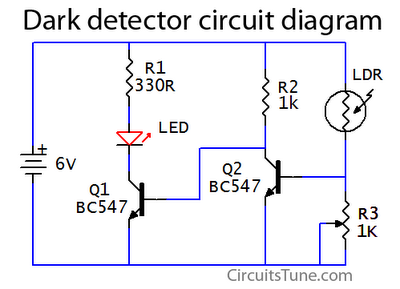
This is a basic dark detector or sensor circuit diagram based on a photoresistor (LDR) and a few components. The dark detector circuit utilizes a photoresistor (LDR) as the primary sensing element. The LDR is a light-dependent resistor that changes...