
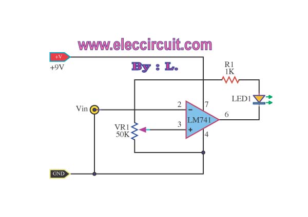
led light circuit schematics
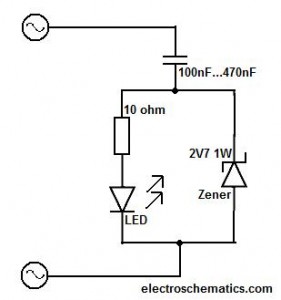
This circuit operates at a mains voltage of 220V, which is standard in many regions. Due to the high voltage involved, it is crucial that only those with sufficient expertise in electronics attempt to work with or modify this circuit. The design is likely to include components such as resistors, capacitors, and possibly transformers, which are essential for managing voltage levels and ensuring safe operation.
Safety precautions must be taken to prevent electrical shock. This includes using insulated tools, wearing appropriate personal protective equipment (PPE), and ensuring that the circuit is de-energized before any maintenance or modifications are performed. Additionally, the circuit should be housed in a secure enclosure to prevent accidental contact with live parts.
The schematic may involve a power supply section that converts AC mains voltage to a lower, more manageable voltage for the rest of the circuit. This could include a transformer to step down the voltage, followed by rectification and filtering stages to provide a stable DC output if required.
In summary, this circuit is intended for advanced users who are aware of the dangers associated with high voltage circuits and have the necessary skills to work safely with them. Proper safety measures and an understanding of the circuit's operation are essential to prevent accidents and ensure reliable performance.Do not try this circuit unless you have good knowledge about electronic devices. This circuit is connected to main power source (220V) and can give you a high electrical shock 🔗 External reference
Related Circuits

The IR Theremin hardware schematic is notably simple, as the primary input and output devices require minimal connections. This simplicity can be a double-edged sword, as fewer hardware components often lead to increased software complexity. The main components utilized...
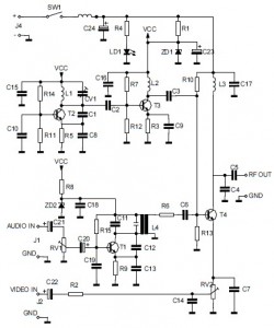
This is the circuit diagram of an audio/video modulator. The circuit converts audio and video signals into a UHF TV signal. It is designed to connect a video signal originating from a camera or other video source to a...
This circuit generates dual-tone bell sounds similar to those found in standard doorbell units. It is applicable in various contexts beyond doorbells. The circuit, as depicted in the diagram, produces a "Ding-tone" when switch P1 is pressed and a...
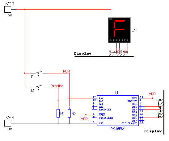
National Instruments Multisim now features microcontroller unit co-simulation capabilities, enabling the inclusion of a microcontroller, programmed in assembly or C code, within SPICE-modeled circuits. The MCU functionality in Multisim allows students, educators, and professional users to program MCUs in...
This simple low voltage tester circuit can be used to monitor batteries and other voltage sources for issues, utilizing an LED display and alarm sound. The low voltage tester circuit is designed to provide a reliable method for monitoring the...
Photo. This is the test circuit -the basic driver is only two transistors, two resistors, the circuit was evaluated using a white LED, but when it was time to button it up and archive it, I replaced the expensive...