
LED Light Show and Audio Amplifier all in one

The Picaxe 18M2 microcontroller is a versatile device that is well-suited for a variety of electronic projects. It is based on a PIC microcontroller architecture and offers a simple programming interface, allowing users to write code in a BASIC-like language. This ease of use makes it particularly appealing for hobbyists and educational purposes.
In this circuit, the Picaxe 18M2 is likely connected to various input and output components. Typical connections may include sensors, switches, and LEDs, which allow the microcontroller to interact with the physical environment. For instance, analog sensors can provide input data, which the microcontroller processes to control output devices such as motors or displays.
The circuit design may also incorporate a power supply circuit to ensure that the Picaxe 18M2 operates within its specified voltage range. This could involve the use of voltage regulators or battery management systems, depending on the application.
Programming the Picaxe 18M2 is accomplished through a dedicated programming interface, usually connected to a PC via USB or serial communication. The programming software allows for the uploading of code, debugging, and real-time monitoring of the microcontroller's performance.
Additional features of the Picaxe 18M2 include built-in support for various communication protocols, such as I2C and SPI, enabling it to interface with other microcontrollers and peripheral devices. This expands the potential applications of the circuit, allowing for complex interactions and data exchange between multiple components.
Overall, the integration of the Picaxe 18M2 in this circuit provides a robust foundation for developing programmable electronic systems, facilitating both simple and sophisticated projects.The hardware within this circuit involved a Picaxe 18M2 IC which is the programmable micro-controller in my design which can be programmed using a PC,.. 🔗 External reference
Related Circuits
It allows car headlights to flash on and off simultaneously or alternately. Components: 555 IC, transistor, resistor, relay, polarized capacitor. The circuit utilizes a 555 integrated circuit (IC) in a monostable or astable configuration to control the flashing of car...
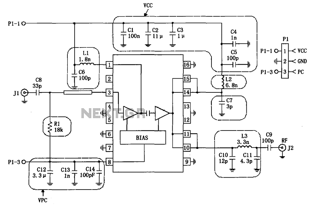
The RF2132 linear power amplifier circuit is depicted in the provided figure. A radio frequency (RF) signal enters through input pin 3 and is processed via a preamplifier. The final stage of the amplifier outputs a gain of 10....
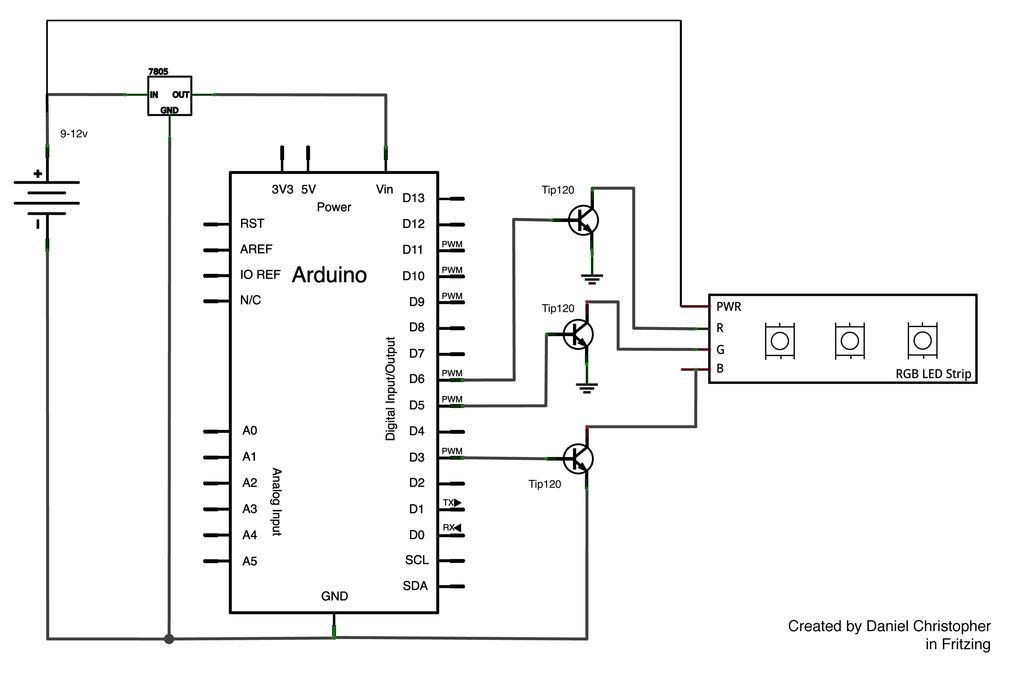
This document outlines the assembly of a circuit designed to pulse width modulate (PWM) a high-power RGB LED strip and program an Arduino to cycle through various colors. The high-power range is specified as 9-12 volts. The procedure includes...

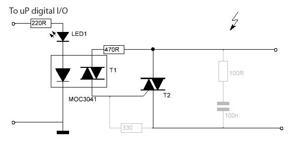
This is a complete telephone bell replacement circuit with minimal external components, featuring an on-chip diode bridge and transient protection, along with direct drive for piezoelectric transducers. The telephone bell replacement circuit is designed to efficiently replace traditional mechanical bells...
To control floodlights using an Arduino, the small switch circuits designed around a 39MF22 were insufficient to manage the required current. To effectively switch floodlights with an Arduino, a more robust circuit design is essential. The initial approach using the...
The following circuit illustrates a USB Powered Audio Power Amplifier Circuit Diagram. Features include multimedia speakers for PCs and a single-chip-based design. The USB Powered Audio Power Amplifier Circuit is designed to enhance audio output for multimedia speakers connected to...